PID Controllers are widely used in industries nowadays. Although there are inbuilt PID controller functions in the PLC, this functions are used in many applications. Approximately 95% of the closed-loop process in industrial automation sector uses this type of controller.
PID stands for Proportional-Integral-Derivative. These three controller is combined in such a way that they can control the process as per user defined value.
Let’s take an example to better understand working of PID Controller.
PID Controller
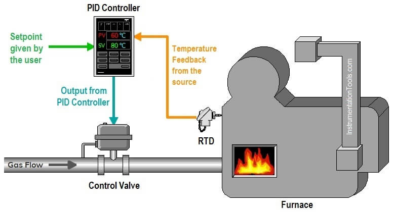
This is a small example of temperature control process using PID controller. We have a furnace here and we want to control the temperature of the furnace. That’s why we have to give some value of temperature that we want to maintain and this value of temperature is called desired value or set value.
Temperature of the furnace we are getting here through a temperature detector, RTD sensor, which is directly connected to PID controller. This is we called a feedback or actual value. This feedback or actual value is compared with the set value and difference between these two signal is our error. PID controller will generate the output based on this comparison and will give output to the control valve.
To maintain the temperature of the furnace, we are controlling here gas flow by a control valve. Position of this control valve is decide here through PID controller output. The response time of the process will merely depend on the three values like Proportional gain, Integral time and derivative time.
Proportional Control (P-Controller) Mode :
Proportional controller generates the control output proportional to the error. This error value is multiplied with the proportional gain to determine the response of the output.
If the gain is set too high, then the output of the controller begins oscillating and become unstable and if the gain set at very low value then the output of the controller will not respond to the changes of the set value.
The use of a proportional controller alone has a large drawback. The offset is a sustained error and will not be eliminated by using a proportional controller alone.
The speed of the response is increased when the proportional gain increases.
Read Also –
Integral Control (PI-Controller) Mode :
Due to the limitation of a proportional controller, a continuous offset is present. The integral controller will continuously increment and decrements the controller output to reduce the error.
If the error value is large, the integral mode will increment/decrement the controller output fast and if the error value is small, the integral mode will slow the function.
For the large integral time, the speed of the response of the controller will slow, and for the small integral time, the speed of the response will be fast.
Read Also –
Derivative Control (PID-Controller) Mode :
There is a limitation of the I-controller that it can’t predict the future behavior of error. So it reacts only once when there is a change in set value.
The derivative controller generates the output based on the rate of change of error and will work fast then PI controller. If there is no change in the error the output of this controller is zero.
The speed of the response is increased with increment in the derivative time. If the value of the derivative time is too large then oscillation will occur and the system will become unstable. For the zero value of derivative time, the output of the controller will become zero.
Read Also –
- Derivative Control Theory
- Loop Tuning Procedure
- Heuristic PID Tuning
- Open-Loop Tuning Method
- Closed-Loop Tuning Method
P vs PI vs PID Controller Graph
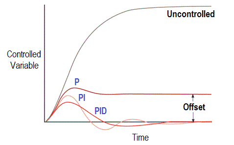
Image Courtesy: isa
Read Also –
- PID Controller Actions
- Tune a PID Controller
- PID Graphical Analysis
- MCQ Questions on PID
- Bumpless Transfer in PID
- PID Selection Logic
Here are some examples where PID-Controller generally used in the industries:
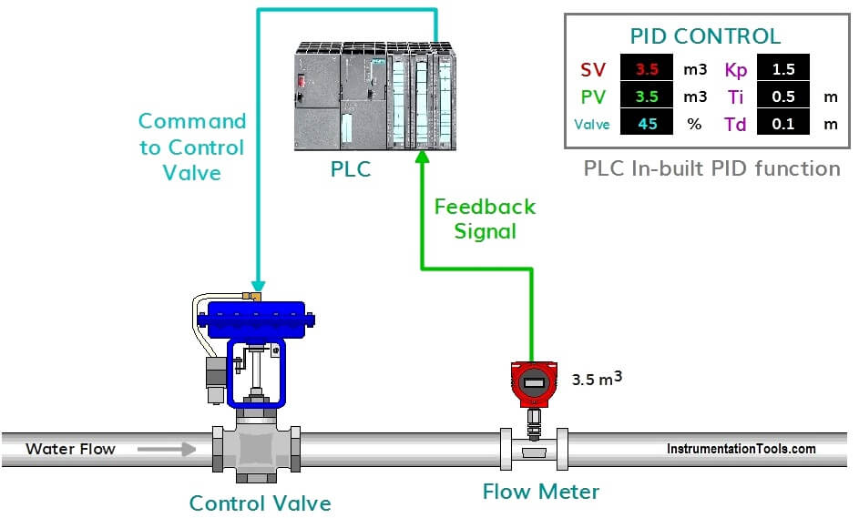
In the above example, we are controlling the flow at a specified value by controlling the position of control valve using the in-built PID function of the PLC.
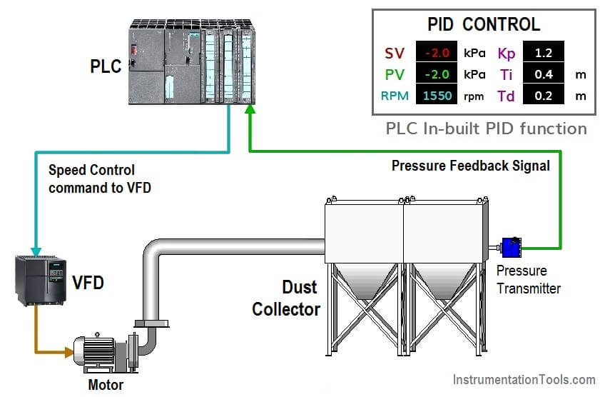
In the above example, we are controlling the suction pressure at a specified value by controlling the speed of the motor using the in-built PID function of the PLC.
There is a lot more example of PID functions in the automation sector in the industry.
If you liked this article, then please subscribe to our YouTube Channel for PLC and SCADA video tutorials.
You can also follow us on Facebook and Twitter to receive daily updates.
Read Next:
Instrument Functional diagrams




Thank you for the excellent article.
Thanks that’s a very good explanation of a very confusing system.
Good
good
Thank you.
I have a question on the practical point of view of pid controller.
are they devices? can you give examples of pid controller? can i use raspberry pi instead of the plc ?
No, they’re not visible devices that you can touch or move. The concept of PID controller is somewhat mathematical. And mathematics is an abstract/idea which can’t be visually appeared or seen but can make a sense and also it’s a pure science, universally recognized when proved.(Suppose, 5 can’t be seen or displayed physically but it makes sense).
Similarly, PID controller is a state/condition that’s determined practically by controlling/analyzing the characteristics/behavior of the system/process as well as user’s desire or target.
The algorithm(logic) is set/built in(built in means given while manufacturing)with the indicating (digital)controllers circuitry or PLC which are devices and can be set with user-defined value when connected with the physical-world. P, PI etc. conditions/state/situations are created by scrolling PV or SV of the indicating controllers(ABB, SHIMADEN, FUJI etc.) as per response of the field values of any process(flow, temp., pressure etc. pneumatic or real physical signals).
I’ve no practical experience of using raspberry pi instead of PLC.