Closed-loop refers to the operation of a control system with the controlling device in “automatic” mode, where the flow of the information from sensing element to transmitter to controller to control element to process and back to sensor represents a continuous (“closed”) feedback loop. If the total amount of signal amplification provided by the instruments is too much, the feedback loop will self-oscillate at the system’s natural (resonant) frequency. While oscillation is almost always considered undesirable in a control system, it may be used as an exploratory test of process dynamics if the controller acts purely on proportional action (no integral or derivative action): providing data useful for calculating effective PID controller settings.
Thus, a “closed-loop” PID tuning procedure entails disabling any integral or derivative actions in the controller, then raising the gain value of the controller just far enough that self-sustaining oscillations ensue. The minimum amount of controller gain necessary to sustain sinusoidal oscillations is called the ultimate sensitivity (Su) or ultimate gain (Ku) of the process, while the time (period) between successive oscillation peaks is called the ultimate period (Pu) of the process. We may then use the measured values of Ku and Pu to calculate reasonable controller tuning parameter values (Kp, τi, and/or τd).
When performing such a test on a process loop, it is important to ensure the oscillation peaks do not reach the limits of the instrumentation, either measurement or final control element. In other words, in order for the oscillation to accurately reveal the process characteristics of ultimate sensitivity and ultimate period, the oscillations must be naturally limited and not artificially limited by either the transmitter or the control valve saturating. Oscillations characterized by either the transmitter or the final control element reaching their range limits should be avoided in order to obtain the best closed-loop oscillatory test results. An illustration is shown here as a model of what to avoid:
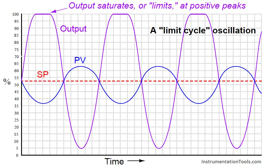
Here the controller gain is set too high, the result being saturation at the positive peaks of the output waveform. The controller gain should be decreased until symmetrical, sinusoidal waves result.
If the controller in question is proportional-only (i.e. capable of providing no integral or derivative control actions), Ziegler and Nichols’ recommendation is to set the controller gain (Note 1) to one-half the value of the ultimate sensitivity determined in the closed-loop test, which I will call ultimate gain (Ku) from now on:
Kp = 0.5Ku
Where,
Kp = Controller gain value that you should enter into the controller for good performance
Ku = “Ultimate” gain determined by increasing controller gain until self-sustaining oscillations are achieved
Note 1 : Note that this is truly the gain of the controller, not the proportional band. If you were to enter a proportional band value one-half the proportional band value necessary to sustain oscillations, the controller would (obviously) oscillate completely out of control!
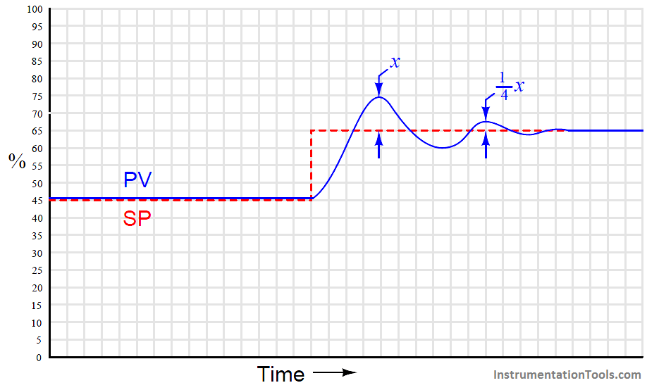
Generally, a controller gain of one-half the experimentally determined “ultimate” gain results in reasonably quick response to setpoint and process load changes. Oscillations of the process variable following such setpoint and load changes typically damp with each successive wave peak being approximately one-quarter the amplitude of the one preceding. This is known as quarter-wave damping. While certainly not ideal, it is a compromise between fast response and stability.
The following process trend shows what “quarter-wave damping” looks like with the controller in automatic mode, with the process variable (PV) exhibiting decaying oscillations following a stepchange in setpoint (SP):
Ziegler and Nichols were careful to qualify quarter-wave damping as less than optimal for some applications.
In their own words
“The statement that a sensitivity setting of one half the ultimate with attendant 25 per cent amplitude ratio gives optimum control must be modified in some cases. For example, the actual level maintained by a liquid-level controller might not be nearly as important as the effect of sudden valve movements on further portions of the process. In this case the sensitivity should be lowered to reduce the amplitude ratio even though the offset is increased by so doing. On the other hand, a pressure-control application giving oscillations with very short period could be set to give an 80 or 90 per cent amplitude ratio. Due to the short period, a disturbance would die out in reasonable time, even though there were quite a few oscillations. The offset would be reduced somewhat though it should be kept in mind that it can never be reduced to less than one half of the amount given at our previously defined optimum sensitivity of one half the ultimate.”
Some would argue (myself included) that quarter-wave damping exercises the control valve needlessly, causing undue stem packing wear and consuming large quantities of compressed air over time. Given the fact that all modern process controllers have integral (reset) capability, unlike the simple pneumatic controllers of Ziegler and Nichols’ day, there is really no need to tolerate prolonged offset (failure of the process variable to exactly equalize with setpoint over time) as a necessary cost of avoiding valve oscillation.
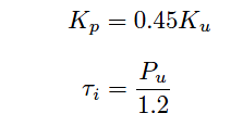
If the controller in question has integral (reset) action in addition to proportional, Ziegler and Nichols’ recommendation is to set the controller gain to slightly less than one-half the value of the ultimate sensitivity, and to set the integral time constant (Note 2) to a value slightly less than the ultimate period:
Where,
Kp = Controller gain value that you should enter into the controller for good performance
Ku = “Ultimate” gain determined by increasing controller gain until self-sustaining oscillations are achieved
τi = Controller integral setting that you should enter into the controller for good performance (minutes per repeat)
Pu = “Ultimate” period of self-sustaining oscillations determined when the controller gain was set to Ku (minutes)
Note 2 : Either minutes per repeat or seconds per repeat. If the controller’s integral rate is expressed in units of repeats per minute (or second), the formula would be Ki = 1.2/Pu .
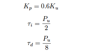
If the controller in question has all three control actions present (full PID), Ziegler and Nichols’ recommendation is to set the controller tuning constants as follows:
Where,
Kp = Controller gain value that you should enter into the controller for good performance
Ku = “Ultimate” gain determined by increasing controller gain until self-sustaining oscillations are achieved
τi = Controller integral setting that you should enter into the controller for good performance (minutes per repeat)
τd = Controller derivative setting that you should enter into the controller for good performance (minutes)
Pu = “Ultimate” period of self-sustaining oscillations determined when the controller gain was set to Ku (minutes)
An important caveat with any tuning procedure based on ultimate gain is the potential to cause trouble in a process while experimentally determining the ultimate gain. Recall that “ultimate” gain is the amount of controller gain (proportional action) resulting in self-sustaining oscillations of constant amplitude. In order to precisely determine this gain setting, one must spend some time provoking the process with sudden setpoint changes (to induce oscillation) and experimenting with greater and greater gain settings until constant oscillation amplitude is achieved. Any more gain than the “ultimate” value, of course, leads to ever-growing oscillations which may be brought under control only by decreasing controller gain or switching to manual mode (thereby stopping all feedback in the system). The problem with this is, one never knows for certain when ultimate gain is achieved until this critical value has been exceeded, as evidenced by ever-growing oscillations.
In other words, the system must be brought to the brink of total instability in order to determine its ultimate gain value. Not only is this time-consuming to achieve – especially in systems where the natural period of oscillation is long, as is the case with many temperature and composition control applications – but potentially hazardous to equipment and certainly detrimental to process quality. In fact, one might argue that any process tolerant of such abuse probably doesn’t need to be well-tuned at all!
Despite its practical limitations, the rules given by Ziegler and Nichols do shed light on the relationship between realistic P, I, and D tuning parameters and the operational characteristics of the process. Controller gain should be some fraction of the gain necessary for the process to self-oscillate. Integral time constant should be proportional to the process time constant; i.e. the “slower” the process is to respond, the “slower” (less aggressive) the controller’s integral response should be. Derivative time constant should likewise be proportional to the process time constant, although this has the opposite meaning from the perspective of aggressiveness: a “slow” process deserves a long derivative time constant; i.e. more aggressive derivative action.
Also Read : Ziegler-Nichols Open-Loop Method


Please provide a source for this information. It looks very familiar to a book I have read.