Explain PLC programming for the Automated Guided Vehicle (AGV) in the manufacturing plant. Here we are discussing some part of the working in AGV as an example program in PLC.

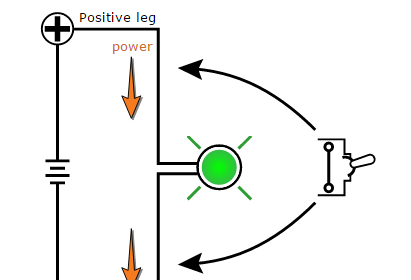
Here we are using the ultrasonic sensor concept for object detection in the way of AGV. The automated guided vehicle work as line follower robot. If there is an object in front of the AGV it will stop running.
For this, we will use the ultrasonic sensor for object detection. When the object is detected, the ultrasonic sensor will give the command to the PLC.
The ultrasonic sensor generates the sound on some frequency which travels through air and if objects in its path it will bounce from the object and back to sensor. From the equation, we can count the distance.
For example – We can calculate the distance as per the equation.
Consider here sound wave takes 294micro second for traveling (total time is taken from the sensor to object and object to the sensor). So here we can calculate the distance.
Time = Distance/speed
Distance = Time*Speed = 294 microsecond * 0.034 cm/microsecond = 9.999cm
Speed of the light = 340 m/s
List of Inputs
Register A:- Measured echo or traveling time.
List of Outputs
Q1:- AGV motor output
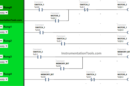
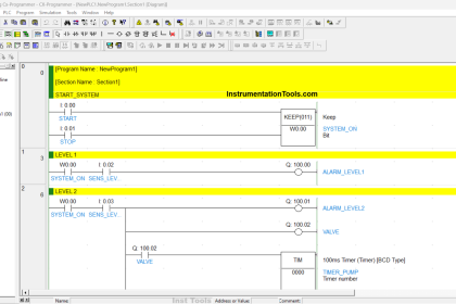
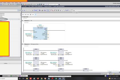
Automated Guided Vehicle with PLC
NETWORK 1:-

DIV mathematics instruction is used for unit conversion. Time speed is converted from m/s to cm/microseconds.
NETWORK 2:-

Multiplication instruction is used to calculate the distance of the object.
NETWORK 3:-

For example, we have taken a 10cm safe distance. If the detected distance is less than 10cm, Object may near to AGV so it needs to be stopped.
Note:- Above application may be different from the actual application. This example is only for explanation and educational purposes only.
Author: Bhavesh
If you liked this article, then please subscribe to our YouTube Channel for PLC and SCADA video tutorials.
You can also follow us on Facebook and Twitter to receive daily updates.
Read Next:
- Data Comparison Instructions
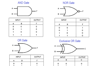
- Simulate Gate Array Logic
- PLC Communication Network
- Analog Measurement in PLC
- Security of SCADA Systems