This is a complete tutorial about PLC ladder logic to control variable frequency drive (VFD) for motor speed control with speed selection from Field Local Panel or SCADA graphics.
Execution Steps :
- Prepare a Control and Power drawing
- Commissioning and Parameters Programming in VFD
- Prepare a PLC program
- Prepare a SCADA design
How to Control VFD with PLC ?

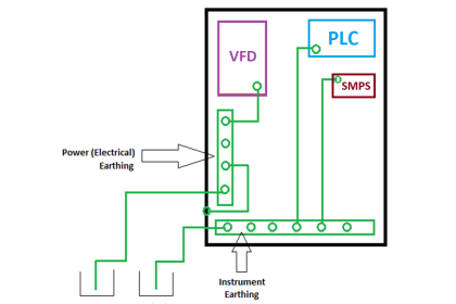
Control and Power Diagram

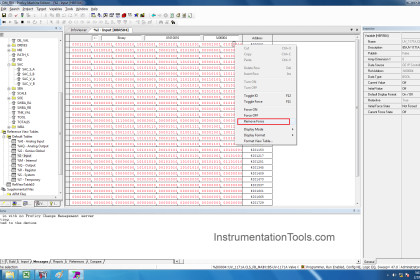
Commissioning and Parameters Programming in VFD
- Commissioning is needed for the proper function of VFD.
- Necessary parameter like Motor Nameplate details, Input Voltage, Motor Type, Frequency should be entered in VFD during quick commissioning.
- After successful quick commissioning, now it’s a time to install the advanced commissioning. This commissioning is needed to give the details of all the digital and analog inputs and outputs, like
- Information about Digital inputs of Start command and Speed Selection command
- Information about Digital Outputs like Status of Drive Running and Drive in Fault etc.
- Information about Analog Inputs like Speed Input 1 and Speed Input 2
- Information about Analog Outputs like Current and Frequency of Motor
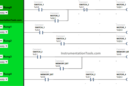
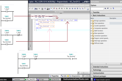
PLC Program
Network 1 :

In this Network 1, we are checking whether the VFD is ready to start. This signal will come when all the conditions are healthy as well as safety and power feedbacks are active.
Network 2 :

In the Network 2, When start button is pressed, VFD Drive_DO bit will be set, if Ready_to_Start and No Error will be there.
Network 3 :

This is the stop logic, When stop button is pressed it will reset the Drive_DO bit.
Network 4 :

In this Network 4, this logic is required for safety as soon as Drive_DO bit will set and if any case VFD will not operate due to any fault then after predefined wait time, here we considered it as Run_FB_Time, it will reset the Drive_DO bit and generate Error.
This Error you can acknowledge from the SCADA after resolving the error from the field side.
Network 5 :

In this Network 5, If the VFD is taking more current and gives overload error, then it will reset Drive_DO bit and generate Error.
This Error you can acknowledge from the SCADA after resolving the error from the field side.
Network 6 :

This is the speed selection Digital output, if you select speed input as a local then it will not activate Speed Selection bit resulting Speed_DO absent and if you select speed input as a remote then it will activate Speed Selection bit resulting Speed_DO present.
SCADA Design
Normal State

This is the normal state of motor. There is no error as well as Ready bit is also in normal state.
Also the speed selection is in LOCAL mode.
Running State
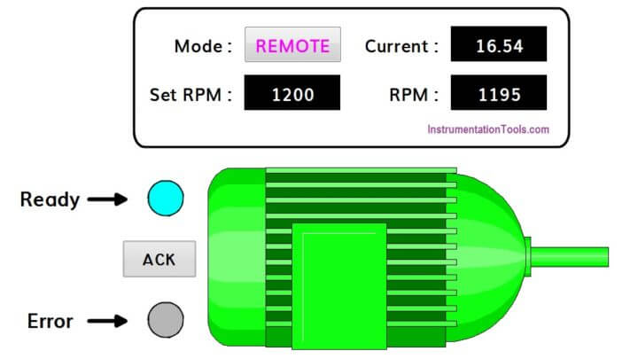
This state shows that Ready bit is high and motor is running without any error.
Error State

There is an error bit is high and motor also showing error condition.
Note :
In some industries, Yellow color also used to indicate the error condition. Red color is used to indicate motor stop condition.
Author : Hiral Patel
If you liked this article, then please subscribe to our YouTube Channel for PLC and SCADA video tutorials.
You can also follow us on Facebook and Twitter to receive daily updates.
Read Next:
Car Washing using Ladder Logic
Ladder Logic for Tanks Filling


Good program
Good
Communication btn drive & plc
nice explanation
Nice program logic
this is a great site, it would be more systematic if the course contents were shown from zero to advance
What do represent Temp1 and Tem2 on the Networks 2 & 3?
Thanks in advance.