Inst ToolsInst ToolsInst Tools
  • Courses
  • Automation
    • PLC
    • Control System
    • Safety System
    • Communication
    • Fire & Gas System
  • Instrumentation
    • Design
    • Pressure
    • Temperature
    • Flow
    • Level
    • Vibration
    • Analyzer
    • Control Valve
    • Switch
    • Calibration
    • Erection & Commissioning
  • Interview
    • Instrumentation
    • Electrical
    • Electronics
    • Practical
  • Q&A
    • Instrumentation
    • Control System
    • Electrical
    • Electronics
    • Analog Electronics
    • Digital Electronics
    • Power Electronics
    • Microprocessor
  • Request
Search
  • Books
  • Software
  • Projects
  • Process
  • Tools
  • Basics
  • Formula
  • Power Plant
  • Root Cause Analysis
  • Electrical Basics
  • Animation
  • Standards
  • 4-20 mA Course
  • Siemens PLC Course
Reading: PLC Based Industrial Conveyor Ladder Logic
Share
Font ResizerAa
Inst ToolsInst Tools
Font ResizerAa
  • Courses
  • Design
  • PLC
  • Interview
  • Control System
Search
  • Courses
  • Automation
    • PLC
    • Control System
    • Safety System
    • Communication
    • Fire & Gas System
  • Instrumentation
    • Design
    • Pressure
    • Temperature
    • Flow
    • Level
    • Vibration
    • Analyzer
    • Control Valve
    • Switch
    • Calibration
    • Erection & Commissioning
  • Interview
    • Instrumentation
    • Electrical
    • Electronics
    • Practical
  • Q&A
    • Instrumentation
    • Control System
    • Electrical
    • Electronics
    • Analog Electronics
    • Digital Electronics
    • Power Electronics
    • Microprocessor
  • Request
Follow US
All rights reserved. Reproduction in whole or in part without written permission is prohibited.
Inst Tools > Blog > PLC Tutorials > PLC Based Industrial Conveyor Ladder Logic

PLC Based Industrial Conveyor Ladder Logic

Last updated: March 4, 2021 3:25 pm
Editorial Staff
PLC Tutorials
1 Comment
Share
6 Min Read
SHARE

This is a PLC Program to start a Belt Conveyor and also make it selectable from where you want to start a conveyor from Local or Remote. Design SCADA graphics also.

Contents
Conveyor Ladder LogicProblem Solution:Control & Power Diagram:PLC Inputs and OutputsPLC Program:SCADA Design :Take a look at some screenshotsSCADA ReadySCADA RunSCADA Error

By using PLC and SCADA, prepare a PLC program to start a belt conveyor. Also make it selectable from where you want to start Local or Remote. All the interlocks must be included in the program and also design a SCADA graphics. 

Conveyor Ladder Logic
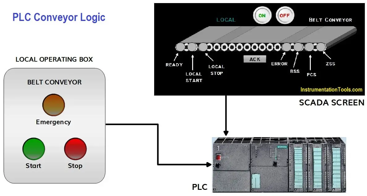
PLC Based Industrial Conveyor Logic

Problem Solution:

  • To make a complete logic first, we have prepared a control as well as power diagram of the starter.
  • Then we define the inputs and outputs.
  • We have done the wiring from PLC to Starter and Feedback from Field to PLC.
  • For the Program, first check all signals from the fields are healthy.
  • Then we have prepared a local start/stop logic.
  • For healthy running, check all the interlocks from the fields are ok.
  • If there will be any fault, then we have activated Error signal.
  • After preparing a PLC program we heave design a SCADA in which all the signals are clearly indicated.

Control & Power Diagram:
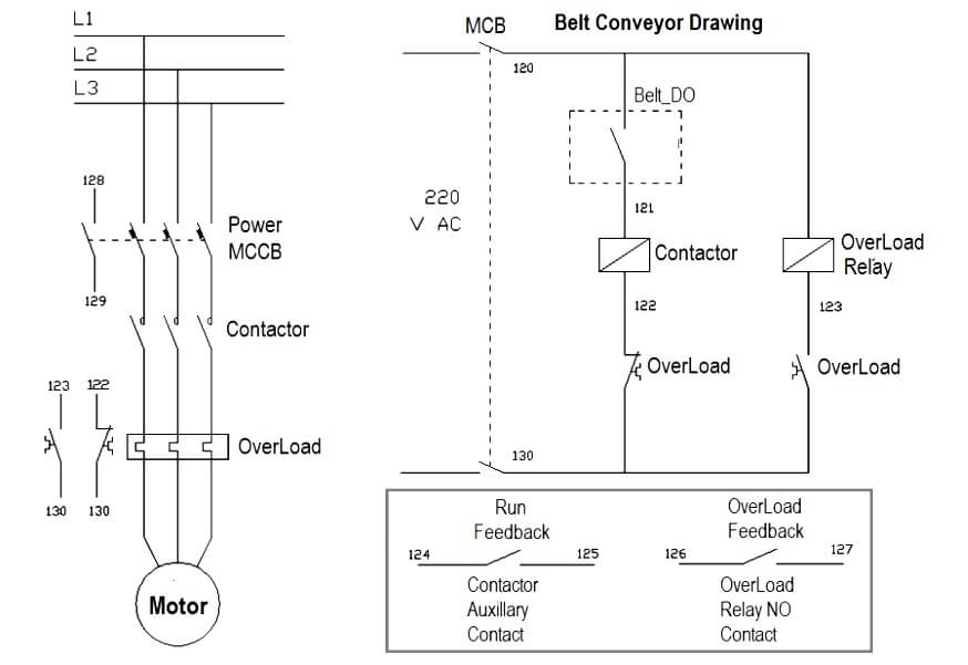
Belt Conveyor Electrical Drawing

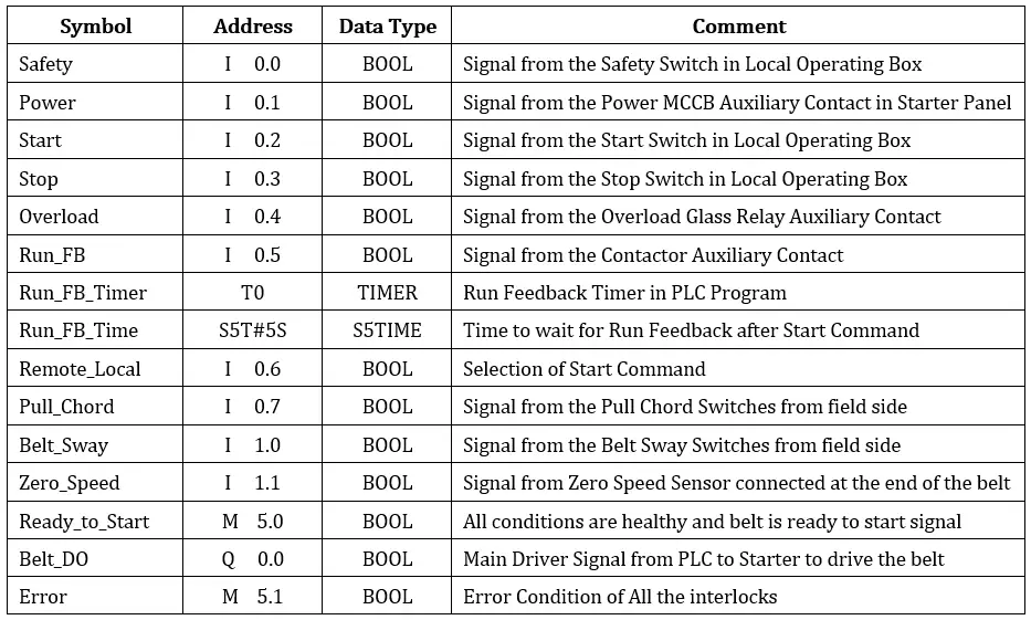
PLC Inputs and Outputs

Industrial Conveyor Ladder Logic

PLC Program:

Here is the PLC program to start the belt conveyor with interlocks.

OB1:
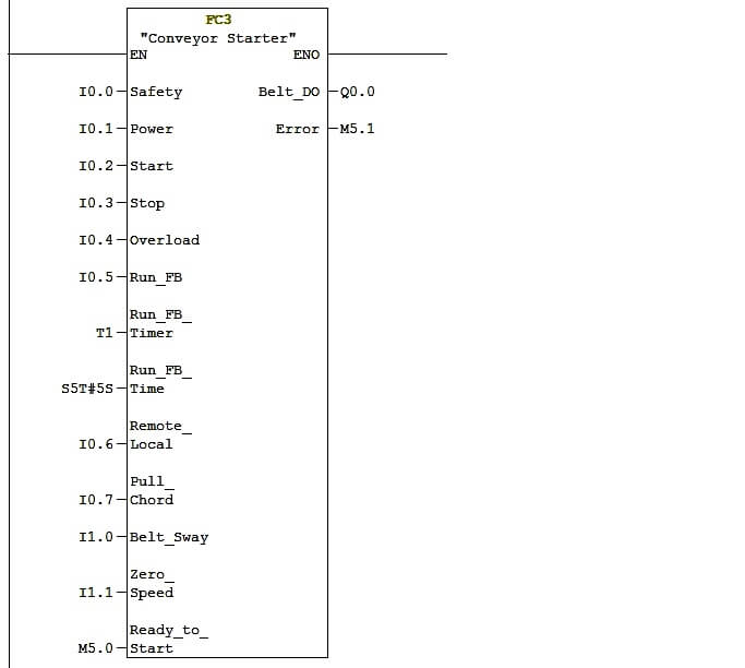
Conveyor Starter Function Block in PLC

Network 1 :

Ready to START status in PLC

In this Network 1, we are checking whether the belt is ready to start.

This signal will come when all the conditions are healthy as well as safety and power feedback’s are active.

Network 2 :

Local Start Logic in PLC

In the Network 2, When selection of start command is in LOCAL mode then this logic will work.

When start button is pressed from the local operating box Belt_DO bit will be set if Ready_to_Start and No Error will be there.

Network 3 :

Local Stop Logic in PLC

This is the local stop logic, this will only work when the selection command is in LOCAL mode.

When stop button is pressed from the local operating box it will reset the Belt_DO bit.

Network 4 :
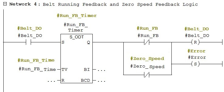
Belt Running Feedback and Zero Speed Feedback in PLC Logic

In this Network 4, this logic is required for safety as soon as Belt_DO bit will set and if any case contactor will not operate due to any fault or Zero speed sensor does not detect pulse then after predefined wait time, here we considered it as Run_FB_Time, it will reset the Belt_DO bit and generate Error.

This Error you can acknowledge from the SCADA after resolving the error from the field side.

Network 5 :
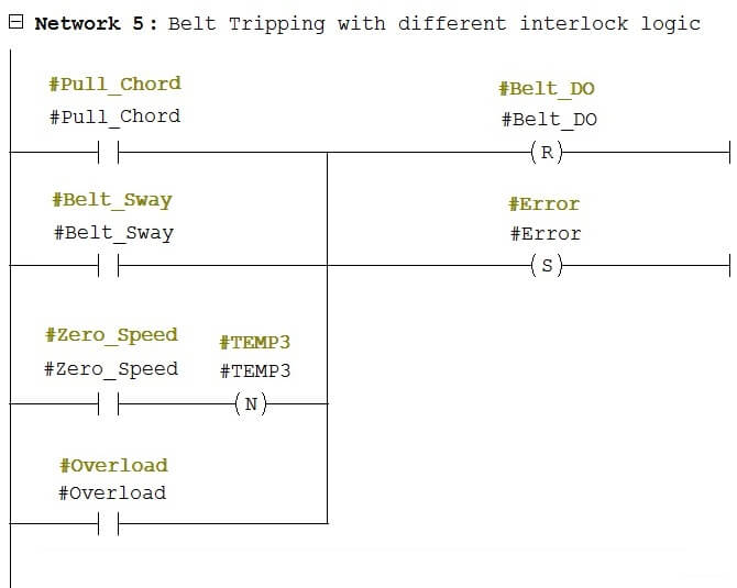
Conveyor Belt Trip Logic with Interlock

In this Network 5, All the interlocks are taken in line. If any one of this interlock will become active, then it will reset Belt_DO bit and generate Error.

This Error you can acknowledge from the SCADA after resolving the error from the field side.

SCADA Design :
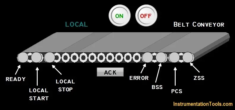
SCADA Design

This is a SCADA screen where operator can operate and visually inspect all the parameter of the conveyor belt.

All the indications are marked just for detailing purpose here.
  • Operator can change the REMOTE/LOCAL mode by just clicking on the LOCAL or REMOTE text.
  • Operator can see the status of READY, ERROR, BSS (Belt Sway Switch), PCS (Pull Chord Switch), ZSS (Zero Speed Switch) as well as LOCAL START and LOCAL STOP button on the operating box.
  • Operator can acknowledge ERROR by just clicking ACK button, just after clearing the error from the field side.
  • Operator can START/STOP the belt conveyor from the ON and OFF button while the selection in REMOTE mode.

Take a look at some screenshots

SCADA Ready
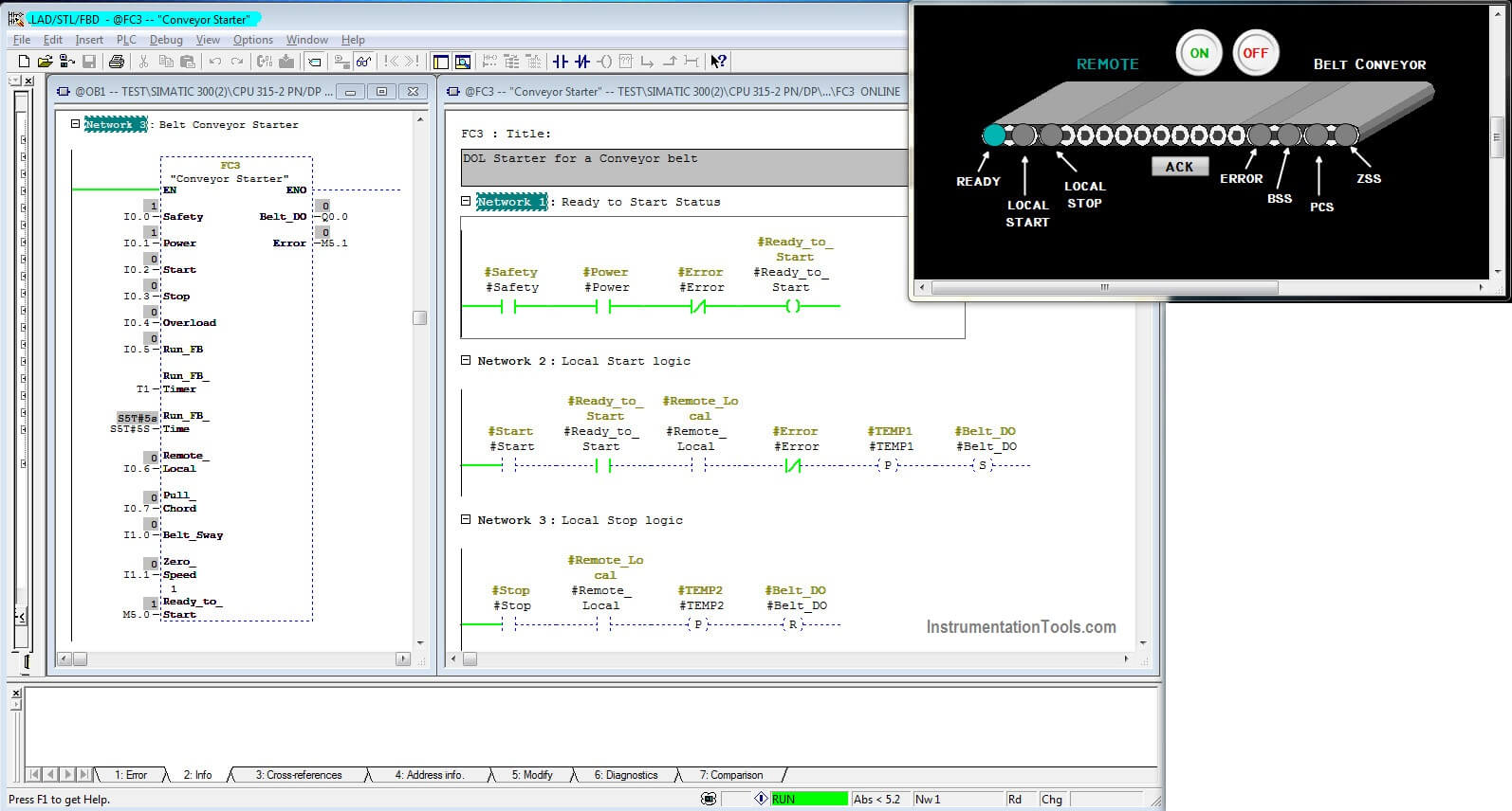
SCADA Ready

This screenshot (above) shows a online monitor of PLC Program as well as SCADA run time screen. There are a healthy signal from Safety button and Power MCCB, so the conveyor belt are showing healthy ready to start indication.

SCADA Run
SCADA Run

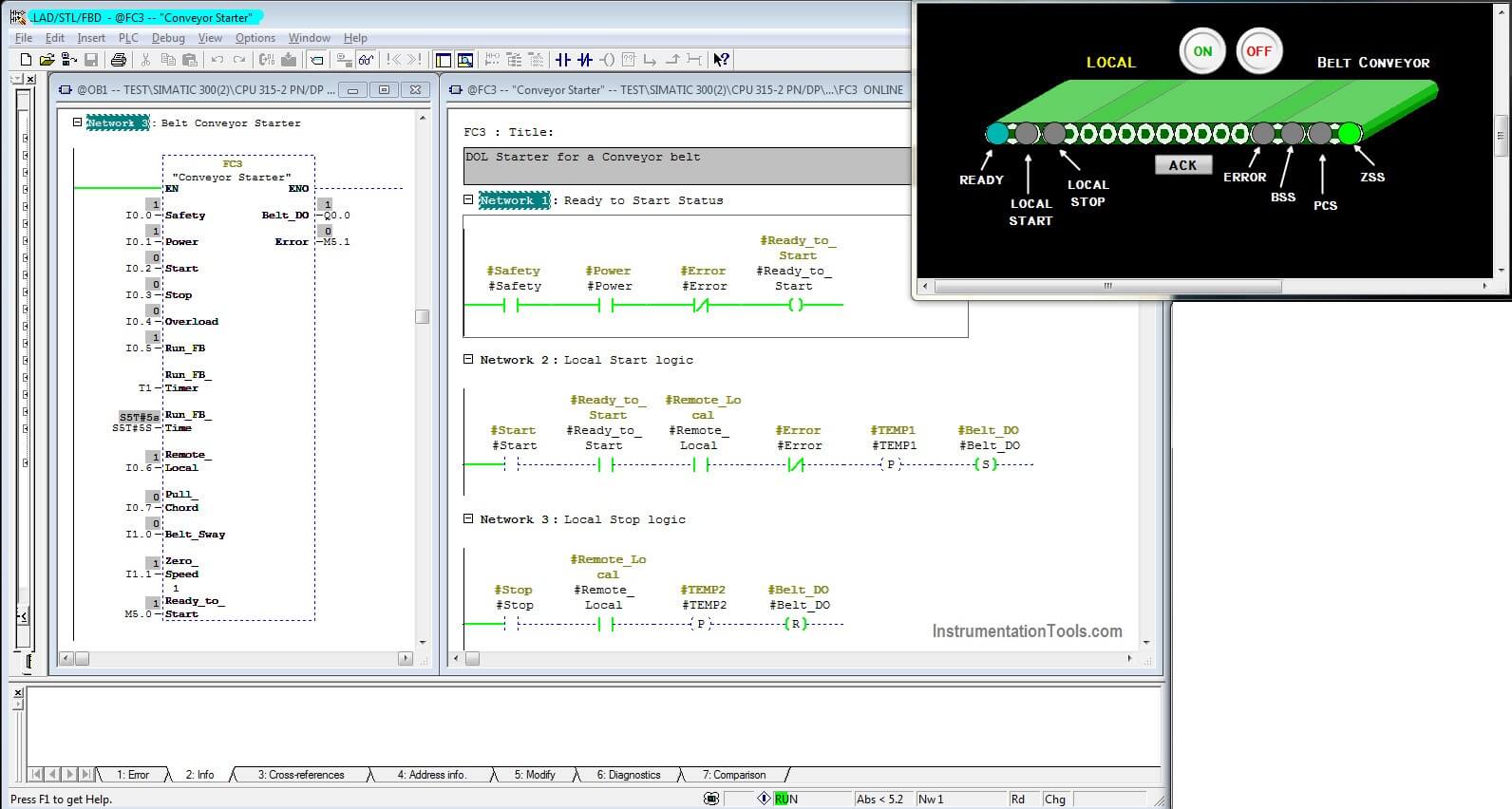
Here we have already given START command from local operating box (as shown in above picture), the belt is showing RUNNING (Green Color in Belt Symbol means it is running smoothly).

There is a healthy ZSS (Zero Speed Switch) signal from the field and there is no ERROR.

SCADA Error
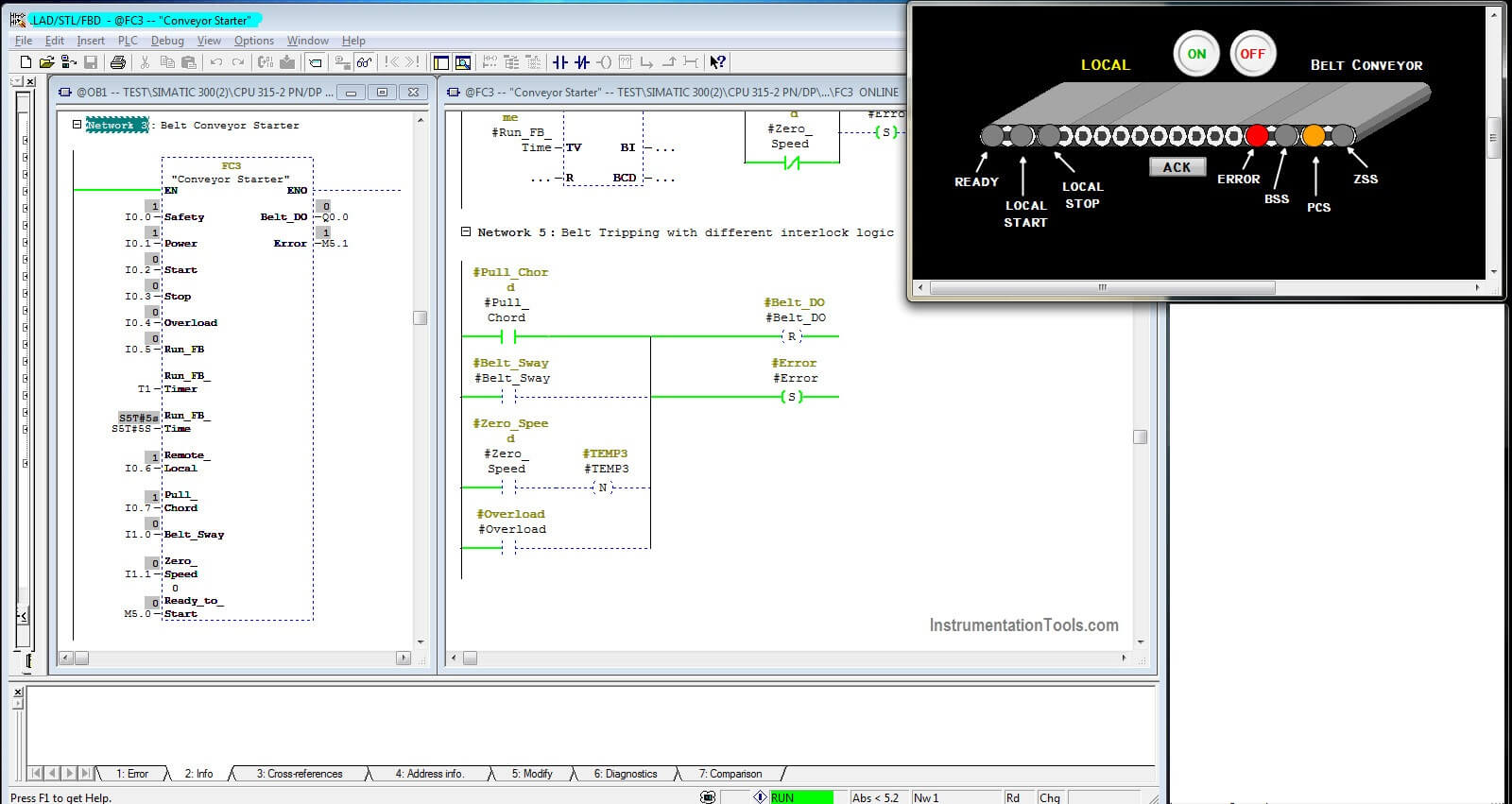
SCADA Error

There is an ERROR bit activated here due to someone is operated PCS (Pull Chord Switch) in the field. So, both ERROR and PCS indication are healthy in SCADA screen as well as we can check in online PLC program as well.

Author : Hiral Patel

If you liked this article, then please subscribe to our YouTube Channel for PLC and SCADA video tutorials.

You can also follow us on Facebook and Twitter to receive daily updates.

Read Next:

Traffic Light Control using PLC

How PLC Reads from Transmitter

PLC Control of 2 Outputs with 1 Input

Facts about PLC Ladder Logic

Contacts and Coils in Ladder Logic
Don't Miss Our Updates
Be the first to get exclusive content straight to your email.
We promise not to spam you. You can unsubscribe at any time.
Invalid email address
You've successfully subscribed !

Continue Reading

Difference between Motion Controller and PLC
Ladder Logic for Stair-Case wiring using Toggle Switches
Difference between DCS & PLC Systems
Types of Cables used in Industrial Automation
Web-based SCADA HMI Software
Data Types in PLC – Bit, Byte, Integer, Real, String
Share This Article
Facebook Whatsapp Whatsapp LinkedIn Copy Link
Share
1 Comment
  • Kieran Maguire says:
    July 5, 2021 at 9:55 pm

    In the power diagram called “belt conveyor drawing,” why is the MCCB numbered as 120 and 130 for its normally open contacts, and not 128 and 129 as it is on the power diagram? Many thanks.

    Reply

Leave a Reply Cancel reply

Your email address will not be published. Required fields are marked *

Stay Connected

128.3kFollowersLike
69.1kFollowersFollow
210kSubscribersSubscribe
38kFollowersFollow

Categories

Explore More

Distributed Control System Interview Questions
How to Operate a Group of Induction Motors using PLC Logic?
VFD Simulator Download – Free Yaskawa V1000 Software
Automatic Railway Crossing Gate Control PLC Program
Types of Failures in Industrial Automation Systems
How Engineers Effectively do Problem-solve and Troubleshoot?
S7-1200 Hardware Configuration – Siemens PLC Tutorials
PLC Logic GATE Program

Keep Learning

InTouch SCADA Password Protection

InTouch SCADA Login Password Security

D flip flop in PLC

D Flip Flop PLC Ladder Logic

How to Filter Digital and Analog Inputs in a PLC

#7 PLC Best Practices – Validate and Alert for Paired Inputs/Outputs

Demo of a SCADA Software – Level Control System

Classification of Fuses

Step-by-Step Guide to Choose Right Fuse for a Panel

HMI Simulation for PID Controller

PID Controller Output Types – PID_PWM and PID_Output

Siemens PLC Force LED

Forcing and Modifying PLC Logic

Two Tanks Filling using PLC

PLC Ladder Logic for Tanks Filling as per Priority

Learn More

Upgrading and Migration of PLC Systems

Upgrading and Migration of PLC Systems

Digital Electronics Multiple Choice Questions

Memory Devices Objective Questions – Part 5

Fan Motor Frequent Journal Bearing Failures

Fan Motor Frequent Journal Bearing Failures Posed Plant Outages

Allen-Bradley MicroLogix 1000 PLC

Questions on Allen-Bradley MicroLogix 1000 PLC

100+ Quiz on Electrical Circuits and Control

100+ Quiz on Electrical Circuits and Control

PLC Ladder Logic Chemical Mixing Process

Chemical Mixing Process using PLC

Lobed Impeller Flow Meters Working Principle

Lobed Impeller Flow Meters Working Principle

Essential Safety Tips for Glass Workers

Essential Safety Tips for Glass Workers

Menu

  • About
  • Privacy Policy
  • Copyright

Quick Links

  • Learn PLC
  • Helping Hand
  • Part Time Job

YouTube Subscribe

Follow US
All rights reserved. Reproduction in whole or in part without written permission is prohibited.
Welcome Back!

Sign in to your account

Username or Email Address
Password

Lost your password?