Communication networks may be used in control systems to pass data between field devices and PLCs, between different PLCs, or between PLCs and personal computers used for operator interface, data processing and storage, or management information.
Although a communications circuit can involve only two pieces of equipment with a circuit between them, the term network typically refers to connecting many devices together to permit the sharing of data between devices over a single (or redundant) circuits.
Data is transmitted over a network using serial communication, in which words of data called bytes consisting of individual logical zeros and ones (bits) are transmitted sequentially from one device to another.
The collection of data in a single transmission is often called a packet. The rate at which data can be transmitted over a network is defined in bits-per-second or bps, but typically expressed in thousands (Kbps) or millions (Mbps).
Industrial Communication Networks
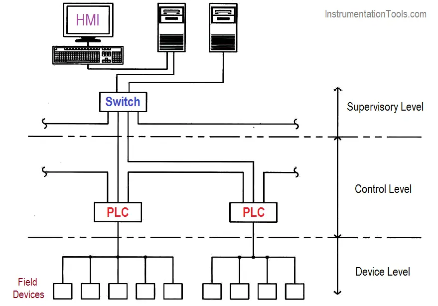
In large SCADA systems, there is usually a communications network of some type connecting the individual PLCs to the operator interface equipment at the central control room.
There may also be networks used at lower levels in the control system architecture, for communications between different PLCs in the same subsystem or industrial facility, as well as for communications between field devices and individual PLCs.
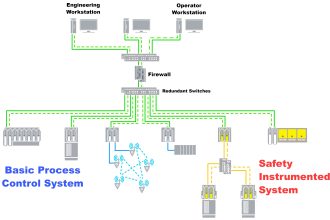
The below figure shows the various levels of network communications in a typical large SCADA system.
Although not widely applied to SCADA systems, two terms that are commonly used with respect to management information systems communication are local area network (LAN) and wide area network (WAN). A LAN consists of all of the devices, typically PCs and servers within a particular industrial facility or site.
A WAN is created by providing a connection between LANs, typically over a long geographic distance using telecommunications industrial facilities. Large SCADA systems may be required to interface to LANs or WANs to provide data transfer to management information systems or to permit internet access to SCADA system data.
Physical media
All communications networks utilize one of two media to transmit data signals between devices: Electrical conductors such as copper wire or optical conductors such as fiber optic cable (wireless communication via radio or microwave radiation does not require an intervening medium).
The point on a device at which the circuit is connected is referred to as a communications port; the physical and electrical characteristics of the communications port must match the media to be used for the network.
Copper Cables
Copper media will support either point-to-point or tapped network configurations. Copper-based networks may be used between devices and PLCs or between PLCs, but should not be installed over long distances, or across an industrial facility boundary. All copper network cables should be of shielded construction.
For copper-based networks, three basic types of copper conductors are used.
Shielded Twisted pair (STP)
Shielded twisted pair (STP), in which individual pairs of insulated conductors are twisted together to reduce inductively coupled interference and covered with a continuous metallic foil shield to reduce capacitively coupled interference.
Individual pairs or multiple pairs are then assembled into a cable within an overall jacket that provides environmental protection.
Unshielded Twisted pair (UTP)
Unshielded twisted pair (UTP), have individual pairs of insulated conductors that are twisted together to reduce inductively coupled interference.
Individual pairs or multiple pairs are then assembled into a cable with an overall jacket to provide environmental protection.
Coaxial cable (COAX)
Coaxial cable (COAX) has a single conductor that is surrounded by an annular layer of dielectric material that is then covered with a metallic braided shield and then an overall jacket.
Configurations are available with multiple coaxial cables within a common overall jacket; these are often referred to as twin-ax (2 cables) or tri-ax (3 cables). Coaxial cable construction is inherently shielded.
Fiber-based Networks
In fiber-based networks, optical fibers transmit data in the form of pulses of light, which are produced by a light-emitting diode (LED) or laser transmitter and detected by a photodiode or phototransistor receiver at the other end of the fiber.
In addition to these photoelectric components, fiber optic transceivers contain the circuitry required to convert electronic data into pulses of light and the reverse. Each optical fiber consists of a glass fiber core with another layer of glass over the core called cladding.
The core and cladding have different indexes of refraction, causing light waves that enter the core to be continuously reflected from the interface and not dispersed outside the core.
Cable sizes are typically defined by the outside diameters of the core and cladding in microns, such as 62.5/125. Optical fiber is available in two types:
Single Mode Fiber
Single Mode Fiber, consisting of a single core strand having a single transmission path, provides very high data transmission rates over long distances, but is costly.
This type of cable is used for long-distance telecommunications and video applications.
Multi-Mode Fiber
Multi-Mode Fiber, consisting of multiple core strands, provides multiple signal paths which result in some distortion of the signal and is therefore restricted to shorter lengths, but is more economical.
This is the type of cable commonly used in SCADA system and data processing networks.
SCADA Networks
SCADA networks operating between industrial facilities on large sites, over long distances, or outside of the industrial facility, the shield should be fiber-based.
Fiber-based networks have some significant advantages for SCADA application, including the following.
- They provide very high signal quality.
- As no electric voltage or current is used, they are completely free of RFI and EMI interference.
- When used over long distances or between buildings they eliminate problems with ground potential differences, ground loops, and transient voltages.
- They provide enhanced security since point-to-point communications cannot be tapped or daisy-chained.
Media Standards
Industry standards for communications media define both the physical and electrical (or optical) characteristics of both the conductors and the connectors used to mate them to communications ports.
Some common network conductor physical standards and their characteristics are listed in the below the table.
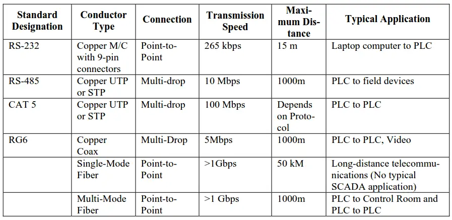
Table 1. Common network communication media
Communication Protocols
Communication protocols define the “rules” by which devices on a network are able to communicate. They define the structure of data packets that are transmitted on the network as well as other necessary information such as how individual devices are uniquely addressed, what signals the beginning and end of a data message, and how each message is checked for transmission errors by the receiving device. A particular communication protocol may be implemented using more than one type of physical media.
For example, Ethernet may operate on UTP, coaxial cable or fiber, but the data structure is the same on any of these media. The protocol used may impose limitations on the media such as maximum data transmission rate (Mbps) or maximum circuit length between devices.
Protocols
Protocols may be either proprietary or open. Proprietary protocols are those developed by vendors for use with their own systems and for which application information is not made publicly available for use by other vendors.
Open protocols are those for which all application information is in the public domain, permitting any vendor to develop devices and software that can use the protocol.
Most of the open protocols used today originated with specific vendors. However, they have been made accessible by those vendors to increase the number of devices that are compatible with their systems, making them more marketable.
Table 2 shows common open network communication protocols.
SCADA Systems
SCADA systems for industrial facilities should use open protocols for a number of reasons:
- There is substantial published data regarding their reliability and performance characteristics.
- Technical support is available from multiple sources.
- There are larger numbers of competing compatible devices to select from.
- Systems may be modified or expanded without requiring sole-source proprietary contracts.
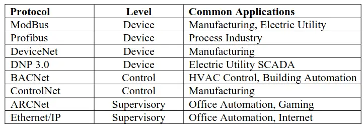
Table 2. Common open network communication protocols
Network Topologies
Commonly used network topologies include star, ring and tapped configurations. A logical network is defined as a group of interconnected devices that are communicating together with the same protocol.
Different logical networks may be interconnected by using protocol converters or translators.
Star Topology
In a star topology, each device on the network is connected to a central hub by a single communications circuit, as shown in the below figure. The hub performs the function of passing messages between devices.
Types of devices that may serve as the hub of a star network include repeaters, switches, and routers.
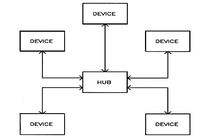
The most common example of this topology is the Ethernet LAN used to interconnect all of the personal computers within an office environment. In this case, a dedicated cable is routed from the Ethernet port on each PC back to a switch or router somewhere in the office building.
In a star network, loss of a single communication circuit affects only the single device at the end of that circuit, although the loss of a hub device obviously affects the entire network. The star network has the highest installation cost per device.
Ring Topology
In a ring topology, two communication ports are provided on each device and the network circuit makes a loop through all of the devices, with an open point, as shown in the below figure.
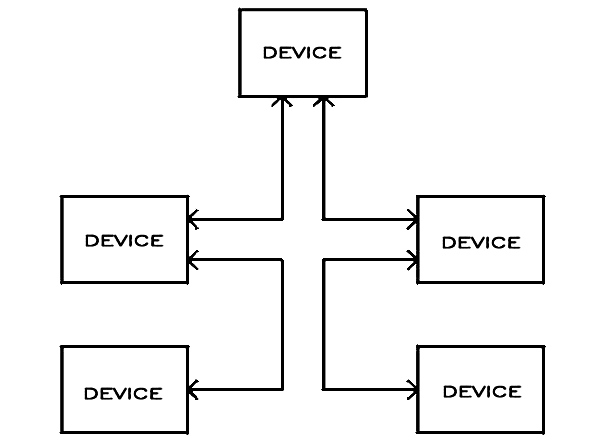
Two-way communication allows messages to pass in either direction along the network. Messages must be passed through the communication ports of each device on the network, making it vulnerable to a break if a single device fails or is removed.
If a means is provided to bridge the open point on the failure of a particular device or circuit segment, this configuration can have high reliability at a relatively low cost.
Multi-drop Topology
In a tapped (or multi-drop) network the communications circuit is tapped to be connected to each device so that the communication ports of the various devices are effectively electrically in parallel. Tapped connections are applicable only to copper-based media; fiber-optic circuits are limited to point-to-point operation.
The configuration in the figure below typically represents the lowest installed cost per device.
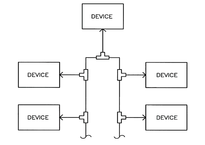
This configuration is commonly used for field device communications; a common example is a fire detection system with addressable devices, in which a UTP network is T-tapped at each device.
Network Redundancy
The need for network redundancy in a SCADA system is dependent on the robustness and vulnerabilities of the type of network used as well as the criticality of the control or reporting functions that rely on the network.
In a system where the network serves only to pass management information reporting or trending of data to a central location, and all automatic control and operator interface functions are fully present with the network out of service, a non-redundant configuration is acceptable.
If a network serves only a single redundant component of a system, such as the point-to-point communication circuit between a generator PLC located in the control room and the local engine control panel, network redundancy is also not required.
Any network, however, that is required for system operation, or whose failure could affect multiple redundant sub-systems or components, must be redundant. For example, a communications network used to pass information (such as generator start signals) between all of the generator PLCs and the system master PLC must provide redundancy.
Star or a Tapped Network with Redundancy
In either a star or a tapped network, redundancy requires complete duplication of the network, including communication ports at each device, communication circuits, and the hub equipment.
The below Figure presents an example of a fully redundant network configuration. In this configuration, one network serves as the primary with all devices using it for communication. If any (or all devices) sense loss of communications with the primary network, they automatically transfer to the backup network.
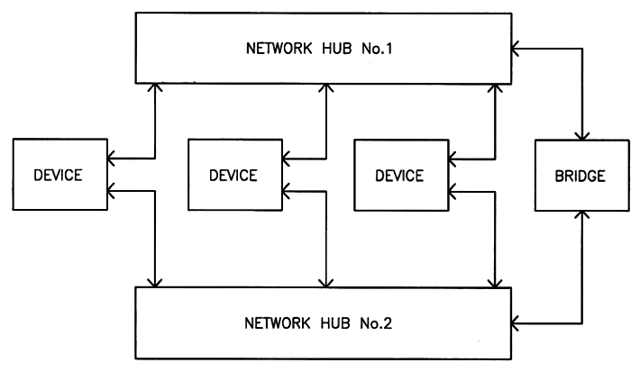
This provides protection both against loss of the entire primary network and loss of an individual device connection. A bridge is required between the two networks to allow a device that has transferred to the backup network to communicate to those remaining on the primary network.
An advantage of this configuration is that each device requires only a single address, as it only communicates with one network at a time.
Ring Network
The reliability of a ring network can be increased by providing an automatic switching device at the open point. The switching device periodically polls the other devices on the network and detects an open point due to device or communication circuit failure by the lack of response from particular devices.
The switch is then automatically closed, restoring communications between all devices. This is referred to as a “self-healing” ring as shown in the below figure.
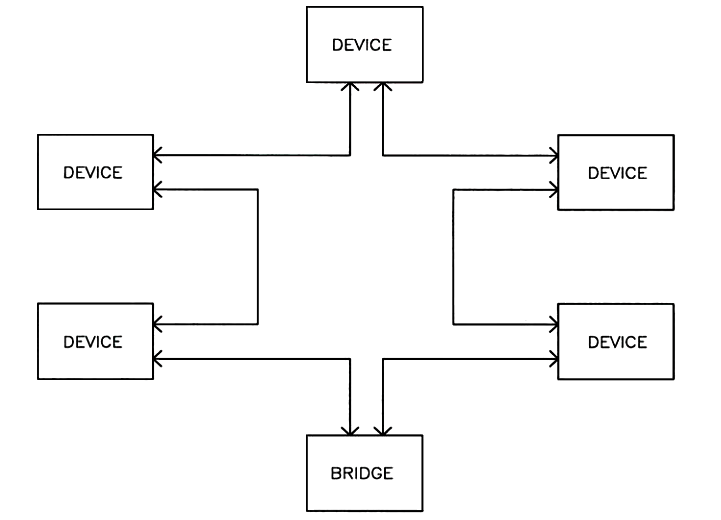
This provides a network that is more reliable than any of the non-redundant configurations, at less cost than a fully redundant configuration, and maybe acceptable for facilities with lower RAM criteria.
Network Speed
The speed at which information can be transmitted on a communications network depends upon the protocol, the physical media, the number of devices on the network and the level of message traffic.
Traditionally, the networks associated with SCADA systems have provided adequate speed for alarm and status reporting and operator control but were not fast enough for critical functions like protective relay tripping or under frequency load shedding.
Advances in electrical utility substation automation have led to the testing and qualification of some network systems to speeds adequate for protective relay trip functions (4 milliseconds) under specified traffic levels.
However, before considering a SCADA system that relies upon the network for critical control and protection functions, the user must verify that the hardware and software to be used has been tested and demonstrated the required speed under worst-case traffic conditions.
Reference : This material adapted from the “Department of the Army, TM 5-601, Supervisory Control and Data Acquisition (SCADA) Systems for Command, Control, Communications, Computer, Intelligence, Surveillance, and Reconnaissance (C4ISR) Facilities, 21 January 2006.”
If you liked this article, then please subscribe to our YouTube Channel for PLC and SCADA video tutorials.
You can also follow us on Facebook and Twitter to receive daily updates.
Read Next:
Basics of Switch or Transmitter
