In this advanced PLC logic, detect different part sizes and sort them as per box sizes and place them in the trays.
The parts are nothing but different size boxes such as small, medium, and large. The robot places different size boxes randomly on the conveyor. Then the system detects the box size and moves to the respective conveyor and places them in the respective trays.
Sorting & Distribution Line PLC Programming
The below simulation shows the sorting and distribution line system operation.
Inputs and Outputs
| Type | Device No. | Device name | Operation |
| Input | X0 | Starting point (Supply) | ON when the part is detected. |
| Input | X1 | Upper | ON when the part is detected. |
| Input | X2 | Middle | ON when the part is detected. |
| Input | X3 | Lower | ON when the part is detected at the right end. |
| Input | X4 | Sensor | ON when the part is detected at the right end. |
| Input | X5 | Sensor | The conveyor moves forward when Y1 is ON. |
| Input | X6 | Detect part | ON when the part is detected in front of the pusher. |
| Input | X10 | Starting point (Unload) | ON when the unloading robot is at the start point. |
| Input | X11 | Part on table | ON when the part is on the table. |
| Input | X12 | Robot operation finished | ON when the robot operation is finished. |
| Output | Y1 | Conveyor forward | The conveyor moves forward when Y2 is ON. |
| Output | Y2 | Conveyor forward | Moves toward the front when Y3 is ON. |
| Output | Y3 | Sorting wing | The conveyor moves forward when Y4 is ON. |
| Output | Y4 | Conveyor forward | The conveyor moves forward when Y5 is ON. |
| Output | Y5 | Conveyor forward | Extends when Y6 is ON and retracts when Y6 is OFF. The pusher cannot be stopped in the mid-stroke. |
| Output | Y6 | Pusher | The robot moves part to tray when Y7 is ON. A process cycle begins. |
| Output | Y7 | Unload command | The robot moves the part to tray when Y7 is ON. A process cycle begins. |
| Output | Y10 | Red | Lit when Y10 is ON. |
| Output | Y11 | Green | Lit when Y11 is ON. |
| Output | Y12 | Yellow | Lit when Y12 is ON. |
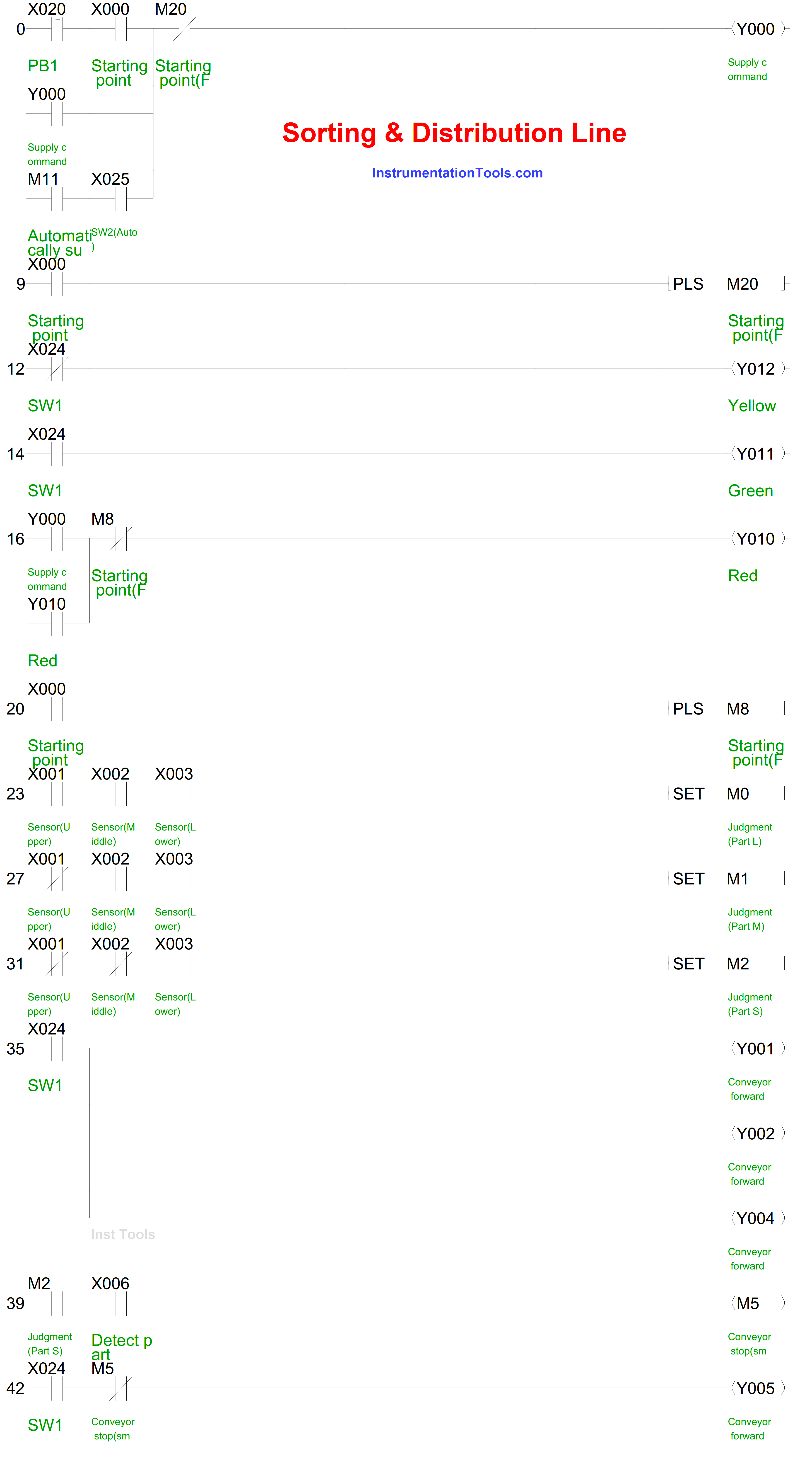
Program Description
Initiating the push button PB1 (X20) on the control panel triggers the Supply command (Y0), thereby setting the robot in motion for moving the object.
Once the robot has completed its task of moving the part and reverting to its original position, the Supply command (Y0) is deactivated. Activating the Supply command (Y0) propels the robot to provide a part.
Activating the switch SW1 (X24) on the control panel instigates the conveyors to proceed forward. Conversely, deactivating the switch causes the conveyors to halt.
Conveyor-carried parts of varying sizes, namely large, medium, and small, are sorted by input from the Upper (X1), Middle (X2), and Lower (X3) sensors and delivered to designated trays.
Large parts are directed to the rear conveyor when the Sorting wing (Y3) on the split conveyor is activated, followed by the part being transported on the conveyor and eventually descending from the right edge.
Medium parts are led to the front conveyor when the Sorting wing (Y3) on the split conveyor is deactivated and subsequently transferred to the tray by the robot.
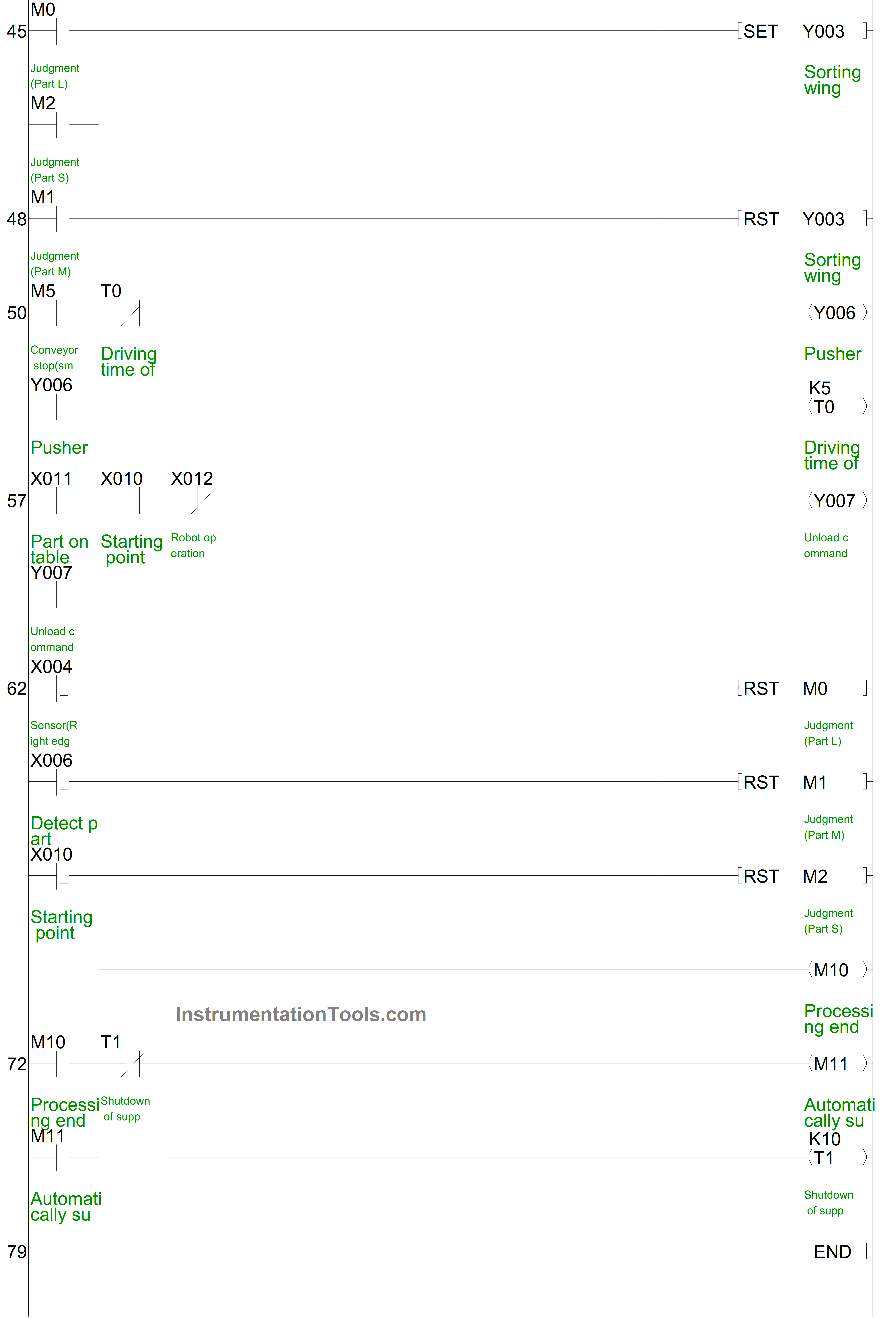
Small parts are routed to the rear conveyor upon activation of the Sorting wing (Y3) on the split conveyor. Once the Detect part sensor (X6) in the split conveyor is activated, the conveyor is brought to a halt and the part is nudged onto the tray.
When the Robot detects a part on the table (X11), the Unload command (Y7) is activated. Once the robot finishes its operations, indicated by the Robot operation finished (X12) status turning on (which happens when a part is deposited on the tray), the Unload command (Y7) is deactivated.
Provided the switch SW2 (X25) on the control panel remains activated, an automatic supply of a new part occurs under the following conditions:
- When the robot initiates the transportation of a medium part.
- When a small part is added to the tray, or a large part descends from the right edge of the conveyor.
The display lights flash in the following manner:
- The red light indicates the robot is in the process of supplying a part.
- Green light signifies the conveyor is in motion.
- Yellow light is illuminated when the conveyor is at a standstill.
PLC Program
Source: Mitsubishi Electric
If you liked this article, then please subscribe to our YouTube Channel for Instrumentation, Electrical, PLC, and SCADA video tutorials.
You can also follow us on Facebook and Twitter to receive daily updates.
Read Next:
- Find the Best PLC for Your Project
- HMI Screens on a Mobile or Tablet
- Top Automation Vendors in World
- Tia Portal Interrupt Organization Block
- Types of Sensors Used in Automobiles