The following covers RTD questions and answers in various aspects.
RTD Questions and Answers

Why is 4-wire connection recommended with Pt100 Class A (acc. to IEC 60751)?
Only 4-wire connection is completely compensating the wire resistance effect of the whole cable circuit. With 2- or 3-wire connections there might be possibility to manually program the measured cable resistance as a transmitter parameter to correct the final readout.
But even in these cases the parameter is correct only at the ambient temperature of the moment of measuring the cable. The measurement circuit loses its accuracy if the ambient temperature changes.
The 4-wire connection compensates also ambient temperature variations.
The Class A Pt100 RTDs are meant for accurate temperature measurement, that’s why the wire connection should always be implemented with 4 wires.
What are the differences between 2, 3, or 4 wire configurations?
RTDs (Resistance Temperature Detectors) are offered with 2, 3, or 4 lead configuration.
The best configuration for a specific application depends on a number of factors, however the sensor configuration must match instrumentation, otherwise lead-wire resistance cancellation circuitry may be ineffective.
Factors to consider :
- Cost of installation – more wires generally means higher cost
- Available space – more or larger wires require more space
- Accuracy requirements – 2 wire configurations may provide the required accuracy, especially with high resistance elements
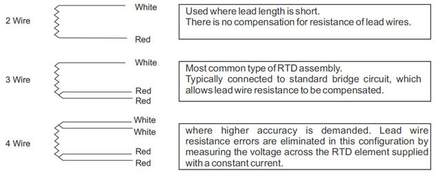
A. 2-lead RTD construction
2 wire RTD result in lead-wire resistance getting added to the element resistance. Consequently, the temperature reading is artificially high.
B. 3-lead RTD construction
3 wire RTD result in canceled lead-wire resistance error only if the instrumentation can measure true 3-wire resistance.
Lead-wire resistance error cancellation is most effective when all the lead wires have the same resistance. Using 3 wires of the same AWG, length, and composition will typically result in lead-wire resistances matched within 5%.
C. 4-lead RTD construction
4 wire RTD result in canceled resistance only if the instrumentation can measure true 4-wire resistance.
True 4-wire resistance measurement will effectively cancel leadwire resistance error even if all 4 wires are not the same AWG, length, and/or composition.
D. Are any RTD configurations interchangeable?
- 4-lead RTDs can generally be used as 3-lead RTDs by eliminating (or tying off) one of the leads
- 4-lead RTDs can be used as 2-lead RTDs, by combining (shorting) the common leads (usually of like color – white/white and red/red)
WARNING: combining the common leads eliminates lead-wire resistance cancellation benefits - 3-lead RTDs can be used as 2-lead RTDs, by combining (shorting) the common leads ((usually of like color)
WARNING: combining the common leads eliminates lead-wire resistance cancellation benefits
How to know what type of alpha (TCR) curve to use ?
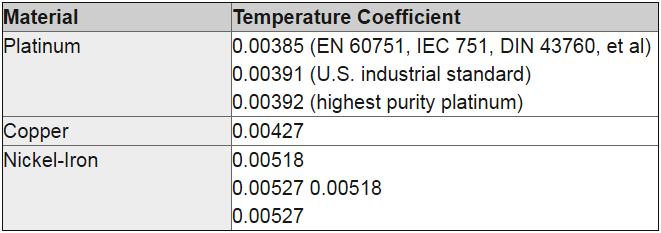
CR (Temperature coefficient of Resistance) is the normalized average change in resistance of a sensing element over a specific temperature range (typically 0 to 100°C).
The value is independent of the base resistance and is a characteristic of the element material itself. The units are measured in ohms/ohm/C.
Example:
A probe may read 100 ohms at 0°C, but at 100°C, the .00385 probe will read 138.5 ohms and the .00392 probe will read 139.20 ohms.
A. Resistance curve depends on instrumentation. Refer to your instrumentation manual for acceptable RTD (Resistance Temperature Detector) input types.
B. Common TCRs include:
When do we need a transmitter for a RTD sensor ?
There are no firm rules on when to specify transmitters. Each temperature monitoring system has unique cost and accuracy requirements, and unique design problems to overcome.
In general, transmitters offer three advantages:
- Eliminate lead effects from temperature readings
- Output is more immune to electrical noise
- Condition the RTD (Resistance Temperature Detector) signal
A. RTD leads effects:
Distance between sensors and control points are an obvious reason to specify transmitters.
Factors to consider:
- Transmitters are more accurate than 2-wire RTDs, if this distance is more than a few feet
- Over large distances, even 3-wire RTD’s can be inadequate for the required accuracy
- 4-wire RTD measurement circuits will effectively eliminate lead wire errors, but the space and cost of two extra leads may exceed the cost of a transmitter
- High resistance sensing elements reduce the effects of lead resistance, but do not eliminate them
- RTD measurement circuits are typically low signal (1 mA or less), and are prone to electrical noise – especially in long wire runs.
- At distances over 500 feet, a transmitter may be the only way to carry the accuracy of the RTD to the control electronics
B. Electrical Noise:
Noise from motors, fluorescent lamps, or other sources will degrade resistance or voltage signals, but has little effect on a transmitter’s controlled current.
You may therefore want to use transmitters over relatively short distances in especially noisy areas. The transmitter may even cost less than specially shielded extension wires.
Simply twisting the transmitter wire pair is very effective at reducing noise; shielded cable is usually not necessary.
C. Signal Conditioning:
You may want transmitters for their signal conditioning circuitry alone. RTD resistance/temperature curves are non-linear.
A transmitter changes the RTD resistance to an industry standard 4-20 mA, while simultaneously linearizing the output with temperature. With the transmitter’s linear response, you don’t need complex equations to interpret readings.
What is class A and class B?
In the world of RTDs (Resistance Temperature Detectors), platinum has gained enormous popularity. This is due to the physical characteristics that make it superior to other materials for sensing temperature.
To provide interchangeability between manufacturers for the sake of global industry, there are some international standards that have been adopted by most countries:
- IEC 60751 defines the temperature accuracy and the resistance/temperature characteristic curve for several tolerance classes
- “Class B” and “Class A” are the most common tolerance classes.
These are defined by a single nominal resistance/temperature characteristic curve and the following accuracy designations:
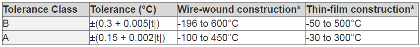
*Consult sensor manufacturer for sensor construction of a particular model
There are a number of standards that either copy or are predecessors of IEC 60751. Among them are IEC 751, DIN 43760, EN 60751, and BS EN 60751.
Another standard, ASTM E1137, uses the same nominal characteristic curve, but defines tolerances differently, and designates them as “Grade B” and “Grade A”.
The ASTM standard is not used as widely as the IEC standard.
When do we need shielded lead wires (electrical noise) for RTD?
Environments containing high voltages or in the presence of electromagnetic fields (EMF) may require shielded lead wires.
These environments generate what is commonly referred to as “noise” (EMI) within a sensing instrument. Lead wires act as antennas.
Two common techniques may help alleviate the influence of electrical noise:
- Twisting the leads will help offset the induced noise.
- Lead wires may be covered with a “shielding,” commonly silver plated copper braid (SPC Braid). Grounding the shielding at the instrument only provides the best results.
What is the self-heating constant?
The self-heating constant defines the temperature rise in degrees Kelvin per mW of applied power. The constant of each RTD Element is measured in a standard condition of ice water at 0 Deg C.
Since the constant is measured under conditions that don’t necessarily reflect a typical application environment, the self-heating constant is primarily used to compare the self-heating properties of one element to another.
In addition, the actual use conditions greatly influence the self-heating constant. For example, potting the element in a thermally conductive material increases the surface area and thermal mass, effectively lowering the self-heating constant.
If an element is used in a full or partial vacuum, however, the opposite can occur—the self-heating constant can increase due to the reduced thermal conductivity of the surrounding medium.
In temperature-sensing applications, self-heating, if excessive, can introduce significant measurement error.
The dependency of self-heating on the thermal conductivity of the surrounding medium can also be exploited to measure fluid level, flow, thermal conductivity, fluid density, etc.
How is the temperature coefficient of a Platinum RTD Element defined?
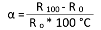
The temperature coefficient, also referred to as the “alpha value”, is the average change in resistance between 0 and 100 °C, and calculated using the formula
How is the resistance vs. temperature characteristic of a Platinum RTD Element defined?
The Callendar–Van Dusen equation describes the relationship of resistance to temperature in Platinum RTD Elements.
For temperatures t equal to and above 0 Deg C, the equation is R(t) = R0*(1+A*t+B*t²)
For temperatures t below 0 Deg C, the equation is R(t) = R0*(1+A*t+B*t²+C*(t-100°C)*t³)
Where A, B, & C are constants for specific RTD curves.
The constants for the IEC 60751 TC 3850ppm curve are:
A = 3.9083*10-3 °C-1
B = -5.775*10-7 °C-2
C = -4.183*10-12 °C-4
What is the difference between the IEC 60751 specification and the DIN EN 60751 specification?
The IEC 60751 and DIN EN 60751 specifications are identical. The DIN specification is basically the IEC spec with a cover page added.
What is the difference between the IEC 60751 specification and the ASTM E1137 specification?
Both specifications apply to the standard 3850ppm temperature coefficient (0.385) platinum curve, and are based upon the ITS-90 temperature scale.
One primary difference between the two specifications is the definition of tolerance classes, as follows
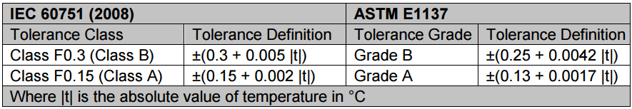
‘F’ indicates thin film element. If the tolerance of a wirewound element is being defined, substitute ‘W’.
A customer asked for a temperature sensor assembly with a platinum RTD element that meets the requirements of DIN 43760. Is this a valid specification for a platinum RTD sensor?
No. DIN 43760 Sept 68 applied to both 100 ohm nickel and platinum RTD elements.
The next version of the specification, DIN 43760 Sept 87, applied only to nickel elements, and no longer applied to platinum elements. DIN EN 60751 is the applicable DIN specification for platinum RTD elements
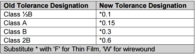
I’ve seen references to a F0.3 tolerance. What does this mean?
“F0.3” tolerance is equivalent to a class B tolerance (F=thin film, W=wire wound, 0.3 indicates ±0.3 Deg C @ 0 Deg C).
The tolerance nomenclature for platinum temperature sensing elements was revised in the IEC 60751 2008-07 specification (also in the DIN EN 60751 2009-05 specification).
The following table relates the old tolerance designation to the new.
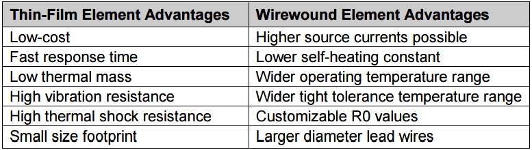
Thin Film or Wirewound Platinum RTD Element—which one should I choose?
The requirement of the specific application dictates the type of element used, but typically the default choice is a Thin Film Element. Intrinsically vibration-resistant and lower in cost than a Wirewound Element.
Thin Film Element meets the needs of most temperature sensing applications.
The following table summarizes the advantages of each type:
What does the name Pt100 stand for?
Pt100 is a resistance temperature detector, made of material Platinum (= Pt_) and its resistance value at 0 °C temperature is 100 ohm (=_100). Hence the name is Pt100.
What means 2-, 3- and 4-wire connection?
A resistance temperature detector (RTD) can be connected with 2, 3 or 4 wires.
The 2-wire connection needs only 2 wires, but then the measuring electronics is measuring also wire resistance, which is not desirable.
Using extra wires for compensating the cable resistance gives more precisely the desired resistance of the RTD itself. The 4-wire connection is the most accurate one.
Also Read : How 3 Wire RTD Lead Wire Resistance Eliminated ?
What are the Pt100 accuracy classes?
Accuracy classes and tolerances defined by IEC 60751:2008 are:
- Class AA ± (0,1+0,0017 * t), ±0,1 °C (0 °C), ±0,27 °C (100 °C), defined on range -50…+250 °C (wire wound resistor), 0…+150 °C (thin film resistor)
- Class A ± (0,15+0,002 * t), ±0,15 °C (0 °C), ±0,35 °C (100 °C), defined on range -100…+450 °C (wire wound resistor), -30…+300 °C (thin film resistor)
- Class B ± (0,3+0,005 * t), ±0,3 °C (0 °C), ±0,8 °C (100 °C), defined on range -196…+600 °C (wire wound resistor), -500…+500 °C (thin film resistor)
- Class C ± (0,6+0,01 * t), not commonly used for industrial measuring circuits.
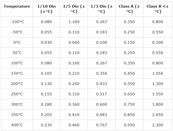
What is 1/3 DIN and 1/10 DIN?
Standard DIN EN 60751:2009 (based on IEC 60751:2008) defines Pt100 resistance accuracy Classes AA, A, B and C and corresponding tolerances.
Before standard update the most accurate class was A and all definitions more accurate were non-standardized, divided Class B values.
- 1/3 DIN is a divided value, based on Class B, not applicable over the whole measuring range. This divided accuracy is only defined at the point: 0 °C = ± 0,3/3 °C= ± 0,1 °C. Class B 1/3 DIN is not a standardized class.
- 1/10 DIN is a divided value, based on Class B, not applicable over the whole measuring range. This divided accuracy is only defined at the point: 0 °C = ± 0,3/10 °C = ± 0,03 °C. Class B 1/10 DIN is not a standardized class.
The standardized Class AA since standard update has made the divided values 1/3 DIN dispensable.
Advantages of RTD ?
An RTD sensing element consists of a wire coil or deposited film of pure metal. The element’s resistance increases with temperature in a known and repeatable manner.
RTDs exhibit excellent accuracy over a wide temperature range and represent the fastest growing segment among industrial temperature sensors.
Their advantages include:
- Temperature range: cover temperatures from -260 to 650°C (-436 to 1202°F).
- Repeatability and stability: The platinum resistance thermometer is the primary interpolation instrument used by the National Institute of Standards and Technology from -260 to 962°C. Ordinary industrial RTDs typically drift less than 0.1°C/year.
- Sensitivity: The voltage drop across an RTD provides a much larger output than a thermocouple.
- Linearity: Platinum and copper RTDs produce a more linear response than thermocouples or thermistors. RTD non-linearities can be corrected through proper design of resistive bridge networks.
- Low system cost: RTDs use ordinary copper extension leads and require no cold junction compensation.
- Standardization: Manufacturers offer RTDs to industry standard curves, most commonly 100 Ω platinum to EN60751
RTD Materials ?
The criterion for selecting a material to make an RTD is:
- The material must be malleable so that it can be formed into small wires
- It must have a repeatable and stable slope or curve.
- The material should also be resistant to corrosion.
- The material should be low cost.
- It is preferred that the material have a linear resistance verses temperature slope.
Some of the common RTD materials are platinum, copper, nickel, Balco (an alloy of 70% nickel and 30 % iron).
These metals have the advantage that they can be manufactured to a very high degree of purity and are, consequently, available with highly reproducible temperature/resistance characteristics.
These metals can also be drawn to a fine diameter wires required in resistance thermometry.
Characteristics of various materials used as RTD
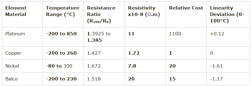
As shown in table, although copper is cheapest, it also has the lowest resistivity and therefore requires inconveniently large sensing elements.
On the other hand, even as nickel and nickel alloy have high resistivity, their resistance versus temperature coefficients are non-linear.
They are also sensitive to strain and their resistivity suffer from an inflexion around the Curie point (358ºC) that makes the deviation of their resistance/ temperature expressions more complicated.
This platinum which not only has a high resistivity (more than six times that of copper) but also a high degree of stability and a wide temperature range.
Although platinum is expensive it can be drawn into fine wires or strips and we only require small amounts for manufacturing RTDs. As a noble metal, it has minimum susceptibility to contamination.
The presence of impurities is undesirable since diffusion, segregation and evaporation may occur in service, resulting in a lack of stability.
The resistivity is also sensitive to internal strains. Thus, it is essential that the platinum should remain in a fully annealed condition i.e. it should be annealed at a temperature higher than the maximum temperature of service.
Temperature Rating for RTD’S ?
The maximum temperature rating for RTD’s is based on two different factors. First is the element material.
Platinum RTD’s can be used as high as 650°C (1202°F). Other materials are much lower in temperature rating and vary from material to material.
The other determining factor for temperature rating is probe construction. There are construction considerations used in each of these different styles making them ideal for use in each of those ranges.
Tolerance table for types of RTD’s according to IEC751 ?
Standard Platinum RTDs
The ITS-90 (International Temperature Scale of 1990- used as a worldwide practical temperature scale in national metrology labs like NIST, NPL) is made up of a number of fixed reference points with various interpolating devices used to define the scale between points.
A special set of PRTs, called SPRTs, are used to perform the interpolation in such labs over the ranges 13.8033 K (Triple point of Equilibrium Hydrogen) to the Freezing point of silver, 971.78 °C.
RTD Standards
There are two standards for platinum RTDs: The European standard (also known as the DIN or IEC standard) and the American standard.
The European standard, also known as the DIN or IEC standard, is considered the world-wide standard for platinum RTDs.
This standard, DIN/IEC 60751 (or simply IEC751), requires the RTD to have an electrical resistance of 100.00 Ω at 0°C and a temperature coefficient of resistance (TCR) of 0.00385Ω/Ω/°C between 0 and 100°C. There are three resistance tolerances for Thin Film.
RTDs specified in IEC60751:
Class AA (Formerly 1/3B) = ± (0.1+0.0017×t) °C or 100.00 ± 0.04Ω at 0°C
Class A = ± (0.15+0.002×t) °C or 100.00 ± 0.06Ω at 0°C
Class B = ± (0.3+0.005×t) °C or 100.00 ± 0.12Ω at 0°C
Also, one special class not included in DIN/IEC60751:
Class 1/10B = ±1/10 (0.3+0.005×t) °C or 100.00 ± 0.012Ω at 0°C
Construction of RTD
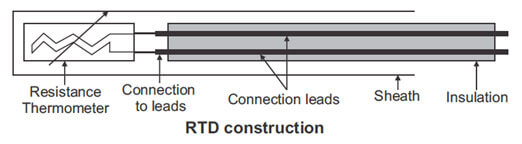
The RTD elements nearly always require insulated leads attached. At temperatures below about 250 °C PVC, silicon rubber or PTFE insulators are used.
Above this, glass fiber or ceramic are used. The measuring point, and usually most of the leads, requires a housing or protective sleeve, often made of a metal alloy which is chemically inert to the process being monitored.
Selecting and designing protection sheaths can require more care than the actual sensor, as the sheath must withstand chemical or physical attack and provide convenient attachment points.
Platinum thin film RTD
The thin film style of RTD is probably the most popular design because of their rugged design and low cost.
The thin film element is manufactured by coating a small ceramic chip with a very thin (.0001”) film of platinum and then laser cutting or chemical etching a resistance path in the platinum film.
The element is then coated with a thin layer of glass to protect it from harmful chemicals and gases.
Larger extension lead wires are spot welded to the chip and this junction is then covered with a drop of epoxy to help hold the wires to the element.
Two wire RTD Wiring
The two wires RTD is the simplest wire configuration. One wire is attached to each side of the element.
A measure can be taken by any device equipped to measure resistance, including basic Volt Ohm Meters (VOM).

This is the least accurate way of measuring temperature, due to the fact that the lead wire resistance is in series with the sensing element.
The lead wire is at a different temperature than the sensing element and also has different resistance verses temperature characteristics. The longer the lead wire greater will be the effect on the measurement.
Three wire RTD Wiring
The three wires RTD is the most popular configuration for use in industrial applications. In order to minimize the effects of the lead resistances, a three-wire configuration can be used.
Using this method the two leads to the sensor are on adjoining arms. There is a lead resistance in each arm of the bridge so that the resistance is cancelled out, so long as the two lead resistances are accurately the same. This configuration allows up to 600 meters of cable.

When used correctly, the three wire configuration eliminates the series resistance.
This permits an accurate measurement of the sensing element. Two of the leads are connected to one side of the sensing element and the single lead to the other side.
The resistance in L1 and L3 should be matched as close as possible; this will cause the lead resistance to cancel them. The color code for a three wire RTD is two red wires and one white.
Four wire RTD Wiring
A four wire RTD is the most accurate method to measure an RTD. It is primarily used in laboratories and is seldom seen in an industrial application.
The four-wire resistance thermometer configuration increases the accuracy and reliability of the resistance being measured: the resistance error due to lead wire resistance is zero.
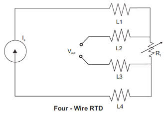
A four wire RTD circuit removes the effect of mismatched resistances on the lead wires.
A constant current is passed through L1 and L4, L2 and L3 measure the voltage drop across the RTD element.
The color code for a four wire RTD is usually two red wires and two white wires. The following diagram illustrates a typical four wire measurement.
RTD Lead configuration and color code
Mineral Insulated RTD
Mineral-Insulated resistance thermometers (M.I.) are equipped in general with Platinum-measuring resistors Pt100 Ω to DIN IEC 751.
The inner (Cu) conductors are embedded in a closely compacted, inert mineral powder (MgO); the measuring resistor will be connected to the inner conductors, is also embedded and is surrounded by the metal sheath to form a hermetically sealed assembly. Sometimes inner conductor of constantan and nickel are also used.
The sheath functions as a useful protective cover in many situations. They are applied in locations where fast response, reduced space and or vibration resistance is a need. They can be furnished with a fixed cable or with a special plug which allows rapid fitting or exchange.
Mineral-insulated RTD temperature probes consist of a flexible, thin-walled stainless steel mineral insulated cable, in which low ohmic conductor copper wires are embedded in pressed, heat resistant magnesium oxide.
The temperature probe is connected to the wires of the internal conductors and accommodated in a stainless steel sheath. Thermowell and mineral-insulated cable are welded to one another.
The good heat transition between the sheath and the temperature probe permits short response times and high measuring accuracy. The vibration resistant (shake proof) design guarantees a long operating life.
Temperature measurements at measuring points difficult to access are possible thanks to the flexible mineral-insulated cable. The smallest bending radius is 5 times the outer diameter.
Metal sheathed RTDs
- It comprises of a thin-walled and flexible mineral insulated sheath cable made up of stainless steel.
- The cable contains low resistance inner wires made of copper embedded in pressed fireproof magnesium oxide.
- The temperature sensor is connected to the inner wires and fitted in a protective tube.
- Protective tube and sheathed cable are welded together hermetically.
- Good heat transfer between protective tube and temperature sensor allows fast response time and high measuring accuracies.
- The flexible probe tube allows temperature measurement at locations that are not easily accessible.
- They are used in difficult measurement application with strong vibrations as well as at all measuring positions where flexibility and ease of replacement are needed.
- Areas of application are to be found in chemical plants, power stations, motors, as well as in machine construction and building installation and in general industrial applications.
Potential source of errors with RTD
Resistance thermometer systems are susceptible to three types of errors: The inherent tolerances built into the thermometers, gradients between the thermometer and the medium to be sensed, and errors introduced along the path between the sensor and readout or control instrument.
Some sources of error are electrical; others result from the mechanical construction of the thermometer.
Interchangeability/Conformity for RTD
A tolerance at the reference temperature is usually 0°C, and a tolerance on the slope or TCR. Below shown figure states that a resistance thermometer conforms most closely to its curve at the reference temperature, while the resistance fans out above and below this reference.
Interchangeability between two thermometers is no more than twice the value of their Conformity. Commercial platinum resistance thermometer elements are available with extremely tight tolerances, to within 0.026°C in some cases.
When interchangeability is an overriding consideration, the specified may consider other means to achieve it. For example, manufacturers may alter their calibration procedures to fix the reference temperature and tightest tolerance at a point other than 0°C.
Sensitivity for RTD
The resistance change per degree change in temperature is a function of base resistance and TCR (Temperature Coefficient of Resistance).
Although a thermometer with higher sensitivity is not necessarily more accurate, a larger signal simplifies output electronics and is less susceptible to lead wire effects and electrical noise.
In addition, a larger resistance produces the same voltage output with less measuring current, which helps to limit self-heating of the thermometer element.
Insulation Resistance for RTD
If the sensing element and leads are not completely insulated from the case, a shunting effect occurs in which the case becomes a parallel resistor and lowers apparent readings. In most industrial thermometers, with specified insulation Resistances in the 100-MΩ ranges, error approaches zero.
The manufacturer must take care to seal water-absorbing materials. The shunting effect decreases with low resistance elements, which accounts. The shunting effect decreases with low-resistance elements
Also Read : Temperature Coefficient of Resistance
Self Heating for RTD
A resistance thermometer is a passive resistance sensor; it requires a measuring current to produce a useful signal.
Because this measuring current heats the element wire above the true ambient temperature, errors will result unless the extra heat is dissipated.
Self-heating is most often expressed in mW/°C, which is the power in mill watts (1000 I2 R) required to raise the thermometers internal temperature by 1°C. The higher the mW/°C figure, the lower the Self Heating.
As an example, assume a 5 mA measuring current is driven through 100 platinum RTD at 100°C.
Self-heating is specified as 50 mW/°C in water moving at 3 ft/sec. The amount of heat generated is:
1000 mW x (0.005 A)2 x (138.5) = 3.5 mW
The self-heating error is:
(3.5 mW) / (50 mW/°C) = 0.07°C
The generated heat increases with higher sensor element resistance (when a constant current measurement device is used), or with increasing measuring current.
The resulting error is inversely proportional to the ability of the thermometer to shed extra heat; which in turn depends on thermometer materials, construction, and environment.
The worst self-heating occurs when a high resistance is packed into a small body. Thin film elements, with little surface area to dissipate heat, are an example.
Self-heating also depends on the medium in which the thermometer is immersed. Error in still air may be over 100 times greater than in moving water.
Time Constant of RTD
A time constant indicates the responsiveness of a resistance thermometer to temperature change.
A common expression is the time it takes a thermometer to reflect 63.2% of a step temperature change in moving water.
Response speed depends on the mass of the thermometer and the rate at which heat transfers from the outer surface to the sensing element.
A rapid time constant reduces errors in a system subject to rapid temperature changes.
Repeatability of RTD
The degree of accord between two successive readings with a thermometer is its repeatability.
Loss of repeatability results from permanent or temporary changes to the resistance characteristics of the element and may be caused by exposing the thermometer to temperatures at or beyond the endpoints of its specified range.
A repeatability test cycles the thermometer between low and high temperatures; any change to R is noted.
A typical repeatability rating for 0°C industrial platinum resistance thermometers is ±0.1°C.
Role Stability of RTD
Stability is long-term drift in thermometer readings. A typical specification would limit drift to 0.1°C per year for rated operation.
Normal services at points well within the temperature rating typically cause much less drift. Drift is a consequence of the element material, with platinum being the most stable; encapsulating materials, which could contaminate the element; and mechanical stress placed on the element by expansion of winding bobbins or other supporting structures.
Packaging and thermal transfer in construction of RTD
Sheaths and other structures surrounding resistive elements should maximize heat transfer from the sensed medium, minimize heat transfer from ambient which can alter readings, and provide necessary protection of the elements.
Proper materials and construction can dramatically improve reading accuracy. One strategy practicable only with wire-wound resistance thermometers versus thermistors, thermocouples, and solid-state devices are temperature averaging. An element may be wound to average temperature over lengths of up to 100feet.
Limitations of RTDs
- RTDs in Industrial applications are rarely used above 660 °C. At temperatures above 660 °C it becomes increasingly difficult to prevent the platinum from becoming contaminated by impurities from the metal sheath of the thermometer. This is why laboratory standard thermometers replace the metal sheath with a glass construction.
- At very low temperatures, say below -270 °C (or 3 K), due to the fact that there are very few photons, the resistance of an RTD is mainly determined by impurities and boundary scattering and thus basically independent of temperature. As a result, the sensitivity of the RTD is essentially zero and therefore not useful.
- Compared to thermistors, platinum RTDs are less sensitive to small temperature changes and have a slower response time. However, thermistors have a smaller temperature range and stability


Hello
during my work on post (I&C Technician) Imanupelate several RTD it is praticable easy to place and robust
good day
How can we Check and Solve RTD and Thermocouple if some showing error reding on Live plant… what is the procedure & and what is the precautions before do any thing…So kindly request to all members please give me right answer… because I am new in Instrumentation…I want learn more about…
When RTD element opened resistance value increases.Resulting malfunction of RTD & also leads to trip the HT MOTOR.How to prevent the malfunctioning OF RTD to prevent unwanted tripping of HT MOTORS.
please may you tell me the accuracy of Pt. ,Cu. ,and Nickel ?