AI, AO, DI, and DO are acronyms used in automation, control systems, and instrumentation. They refer to the types of input and output signals handled by control and monitoring devices such as programmable logic controllers (PLC), distributed control systems (DCS), and data acquisition systems (DAQ).
What is an Analog Input (AI)?
An analog input (AI) is a signal that can have a continuous range of values. These signals are used to read the status of sensors that provide a variable reading, such as temperature sensors (thermocouples, RTDs), pressure sensors, or flow meters.
What is an Analog Output (AO)?
An analog output signal (AO) can also have a continuous range of values and is used to control devices that can be set to variable positions or conditions, such as variable speed drives, or control valves. An analog output could be used, for instance, to set the speed of a motor or the position of a control valve.
What is Digital Input (DI)?
A digital input (DI) is a type of signal that can only have discrete values, typically binary, like 0 (representing off, low, false) and 1 (representing on, high, true). It is used to read the status of binary sensors like limit switches, proximity switches, or photoelectric sensors in a control system.
What is Digital Output (DO)?
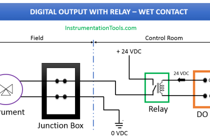
A digital output (DO) is a signal that can also have discrete binary values and is used to control devices such as actuators, solenoids, or LEDs. For instance, a digital output could be used to turn a motor on or off.
These signals are common in industries where automation is applied, such as in manufacturing, process control, and industrial automation. They refer to the basic types of signals used to interact with and control the processes and equipment in these industries.
Examples of AI, AO, DI, DO
Here are some practical examples of Digital Input (DI), Digital Output (DO), Analog Input (AI), and Analog Output (AO) in automation and control systems:
Examples of Analog Input Signals
- Temperature Sensor (Thermocouple, RTD): These devices can give a variable output voltage or current signal that is proportional to the temperature they are measuring.
- Flow Meter: Provides a variable voltage or current signal proportional to the flow rate of a fluid.
- Pressure Sensor: This sensor generates an analog output signal that varies in proportion to the pressure it is measuring.
Examples of Analog Output Signals
- Variable Speed Drive: A variable voltage or current signal can be used to control the speed of a motor.
- Control Valve: An analog output can be used to set the position of a control valve, controlling the flow rate of a fluid.
- Heater Element: In some cases, an analog output could be used to control the power to a heating element, adjusting the heat output based on the control signal.
Example of Digital Input Signals
- Limit Switch: This can send a digital input signal to a PLC when a machine part reaches a specific limit.
- Proximity Sensor: Used to detect the presence or absence of an object without physical contact. When the object is within a certain range, the sensor sends a “1” signal, otherwise, it sends a “0”.
- Push Button: A manually actuated device that sends a binary signal (on/off) to a control system.
Examples of Digital Output Signals
- Actuator/Solenoid Valve: A digital output can be used to open or close a valve (1 for open, 0 for closed).
- Motor Start/Stop: A digital output can send a signal to start or stop a motor.
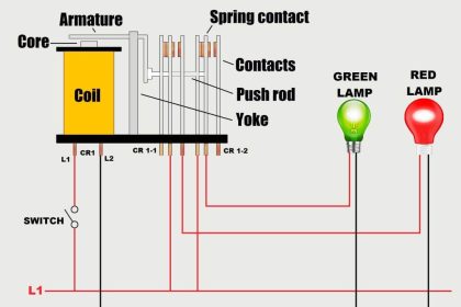
- Indicator Lights: A digital output can be used to control an indicator light on a control panel (1 for on, 0 for off).
These are just a few examples. The specific types of inputs and outputs used will depend on the nature of the system and the requirements of the application.
Purpose
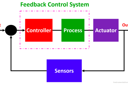
The purpose of Digital Inputs (DI), Digital Outputs (DO), Analog Inputs (AI), and Analog Outputs (AO) is to enable communication and control between a controller (like a PLC, DCS, or microcontroller) and devices in a system or process. They serve as the fundamental interface between the physical world and the digital control system.
The Purpose of Analog Input (AI)
Analog inputs are used to monitor continuously variable conditions. Sensors that monitor conditions such as temperature, pressure, or flow rate provide an analog voltage or current that represents the measured condition. These analog signals are then read by the controller to monitor the state of the system or process.
The Purpose of Analog Output (AO)
Analog outputs are used to control devices that operate over a range of conditions rather than simply on or off. These could control the speed of a motor, the position of a control valve, or the power to a heating element, for example. The analog output provides a variable voltage or current that commands the device to a particular state within its operating range.
The purpose of Digital Input (DI)
Digital inputs are used to receive digital signals from various field devices, usually for the purpose of monitoring. Devices such as push buttons, limit switches, and proximity sensors provide digital input signals to indicate the status of equipment or a process (for instance, if a machine part has reached its limit or if an object is present or not).
The Purpose of Digital Output (DO)
Digital outputs are used to send digital signals to devices to control their operation. A digital output could control the operation of a motor, open/close a valve, or light up an indicator light, for example. The digital output would typically command the device to be either on or off.
Comparison between AI, AO, DI, DO
The below table shows the comparison of AI (Analog Input), AO (Analog Output), DI (Digital Input), and DO (Digital Output).
| Type | Description | Examples | Usage |
|---|---|---|---|
| AI | Receives and interprets a continuous range of values from the physical world, typically from sensors. | Temperature sensor, pressure sensor, level sensor. | Used for process variables that vary continuously. |
| AO | Sends a continuous range of values to control devices. | Variable speed drive (VSD), control valve, damper. | Used to control equipment that can operate at various levels. |
| DI | Receives binary (on/off) signals from the physical world. | Limit switch, push button, proximity switch. | Used for devices that have only two states: on or off. |
| DO | Sends binary (on/off) signals to control devices. | Solenoid valve, motor starter, indicator light. | Used to control devices that can be either turned on or off. |
If you liked this article, then please subscribe to our YouTube Channel for Instrumentation, Electrical, PLC, and SCADA video tutorials.
You can also follow us on Facebook and Twitter to receive daily updates.
Read Next:
- Find the Best PLC for Your Project
- HMI Screens on a Mobile or Tablet
- Top Automation Vendors in World
- Tia Portal Interrupt Organization Block
- Types of Sensors Used in Automobiles