RATE OR DERIVATIVE ACTION
Consider a control system subjected to a disturbance, which causes the error to increase in a ramped manner. Proportional control would respond to this ramped error with a similarly ramped output signal whose slope is proportional to the controller gain. We could reduce the final deviation from the setpoint, i.e., the offset, and the recovery time, if we can provide some extra control signal related to the rate of change of the error signal. This is termed rate or derivative action and is usually incorporated with proportional control.
Rate action is an anticipatory control, which provides a large initial control signal to limit the final deviation. The typical open loop response is shown in Figure.
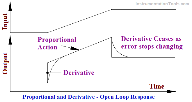
It can be seen that the derivative action gives a large, immediate, control signal, which will limit the deviation. Proportional action is then superimposed upon this step. When the error stops changing derivative action ceases. Note that the displayed step response unobtainable in practice because the normal response approximates and exponential rise and decay.
The rate response gives an immediate control signal, which will be equal to what the proportional response would be after some time, say, T minutes. Derivative units are given in minutes. These are the minutes advance of proportional action. Derivative action is a leading control and, therefore, tends to reduce the overall lag in the system the system is somewhat more stable.
Mathematically proportional plus derivative (PD) control is expressed as:
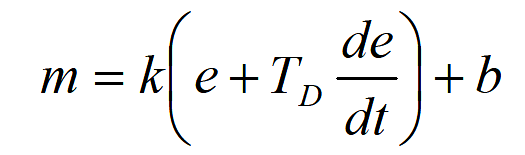
m = controller signal
k = controller gain
TD = derivative time
e = error
b = bias signal
The use of derivative control is limited. At first glance, derivative control looks attractive. It should help reduce the time required to stabilize an error. However, it will not remove offset. The control signal from derivative action ceases when the error stops changing, which will not necessarily be at the setpoint.
Its use, in practice, is also limited to slow acting processes. If used on a fast acting process, such as flow, control signals due to derivative action will often drive the control valve to extremes following quite small but steep (large de/dt ) changes in input.
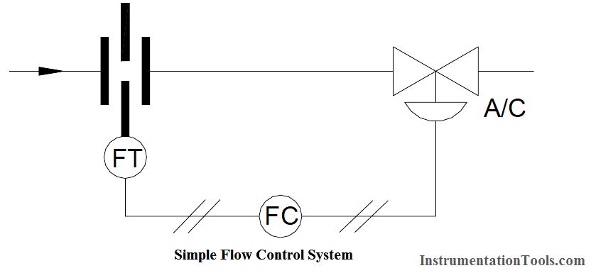
Example:
Consider a simple flow control system, consisting of an orifice plate with flow transmitter and square root extractor plus direct acting controller and air to close valve (refer to Below Figure). This system is subjected to a small, but fast, process disturbance. How will this control scheme perform under proportional and derivative control modes?
Let us consider the PD response to a fast change in process signal in an open loop system
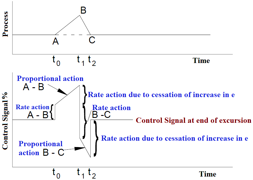
Graph : The open Loop Response of Proportional Plus Derivative (PD) Action to Rapidly Changing Error Signals
The upper portion of Graph shows a positive process excursion, AB, from the zero error condition, followed by an equal negative excursion, BC, which returns the error to zero. Note that the rate of change, i.e., the slope of the process change, from B to C is twice the rate of change of the process, from A to B. Mathematically:
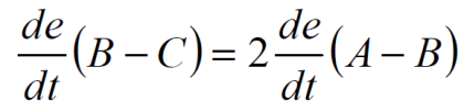
The proportional control action from B to C will be equal but opposite to the proportional control action from A to B. The rate or derivative control action from B to C will be double that from A to B. The resulting open loop control signal pattern is shown in the lower portion of Graph. The controller gain and derivative settings remain constant.
Very shortly after time (t0) the control signal increases abruptly to a value determined by the rate of change of the error (e), the derivative or rate time setting, and the controller gain. Proportional action ramps the control signal up, until time (t1), to a value determined by the error (e) and the controller gain setting. This includes the direction of the error and controller action.
At time (t1) the rate of change of the process error, de/dt, momentarily becomes zero, so the original change in the control signal due to the rate action drops out. Then, the process error change direction becomes negative, and the derivative control action now produces an abrupt negative control signal, double the original derivative control signal. The proportional control action then ramps the control signal down until time (t2).
At time (t2) the rate of change of the process error becomes zero, so the derivative control signal again drops out leaving the control signal at its original bias (zero) error value. Note that this final bias, (zero) error value of the control signal and, hence, the control valve position at the end of this excursion, is determined solely by the proportional. The valve has been stroked rapidly and repeated by the derivative action subjecting it to unnecessary wear, with no improvement in control.
The response of the closed loop shown in the above Example would be somewhat different because the resulting valve action would continuously alter the error signal. However, the valve would still be subjected to rapid and repeated stroking unnecessarily.
Thus, it can be seen from the above discussion that the use of derivative action on fast acting processes such as flow is not advisable.
Let us look at the control of a sluggish (generally a physically large) system. As an example, consider a large tank with a variable outflow and a control valve on the inflow. A large volume change will, therefore, be necessary before any appreciable change in level occurs.
Consider a large change in the outflow. After some delay (due to the sluggishness of the system) the controller will respond.
If we have only proportional mode on the controller the delays will mean that the controller is always chasing the error initiated by the outflow disturbance. The response to proportional control is shown in Below Figure. Note that the process has not fully stabilized after a considerable period of time.
The addition of derivative action, however, causes an anticipatory response. The control signal increases more rapidly and the process is returned to a steady state in a much shorter time. Note also that: The system is more stable (less cycling) with PD control. Offset still exists.
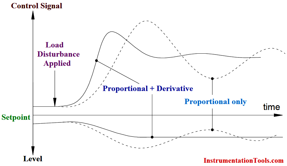
Fig: Large System Under Proportional and Proportional Plus Derivative Control
Summary:
- Derivative or rate action is anticipatory and will usually reduce, but not eliminate, offset.
- Its units are minutes (advance of proportional action).
- It tends to reduce lag in a control loop.
- Its use is generally limited to slow acting processes.