When electric motor is started, it draws a high current typical 5-6 times greater than normal current.
In DC motors there is no back emf at starting therefore initial current is very high as compared to the normal current.
To protect the motor from these high starting currents we use a star and delta starter.
Simply in Star connection, supply voltage to motor will be less. so we use star connection during starting of the motor, after motor running we will change the connection form star to delta to gain full speed of the motor.
Read Full Article : How Star – Delta Starter Works ?
Star Delta Motor Starter
The following figure shows the winding connections in star and delta configuration one by one.

It can be seen that in star connection, one end of all three windings are shorted to make star point while other end of each winding is connected to power supply.
In delta configuration, the windings are connected such that to make a close loop.
The connection of each winding is shown in above figure. In actual motor the three phase connections are provided in the following order as shown

So in order to make winding connection in star and delta style in practical motor, the connection is shown above.

Main contractor is used to supply power to the windings. It must be turned on all the time. Initially the star contactor is closed while delta contactor is open It makes the motor windings in star configuration.
When the motor gains speed, the star contactor is opened while delta contactor is closed turning the motor windings into delta configuration.
The contactors are controlled by using PLC. The following section of PLC tutorial will explain the ladder programming for star delta motor starter.
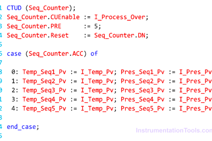
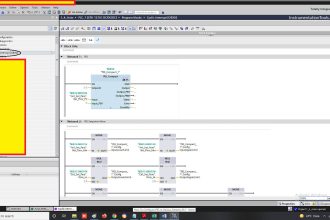
PLC program for star delta motor starter :

PLC Ladder Logic

Rung 1 Main contactor :
The main contactor depends upon the normally open input start push button (I1), normally closed stop button (I2) and normally closed overload relay.
It means that Main contactor will only be energized if start button is pressed, while stop is not pressed and overload relay is not activated. A normally open input named (Q1) is added in parallel to the start button I1.
By doing so, a push button is created which means that once motor is started, it will be kept started even if start button is released
Rung 2 Star contactor:
Star contactor depends upon main contactor, normally close contacts of timer (T1), and normally close contacts of output delta contactor (Q3).
So star contactor will only be energized if main contactor is ON, time output is not activated and delta contactor is not energized.
Timer T1:
Timer T1 measures the time after which the winding connection of star delta starter is to be changed. It will start counting time after main contactor is energized.
Rung 3 Delta contactor:
Delta contactor will be energized when main contactor (Q1) is energized, timer T1 is activated and star contactor (Q3) is de-energized.
Also see Programing of push button and other requirements for simple motor starter is explained in PLC Tutorial: Motor starter
Note : This post for educational or reference purpose only. For a live circuit, there will be some additions to the above circuit like safety related, as per application, some interlocks etc.
If you liked this article, then please subscribe to our YouTube Channel for PLC and SCADA video tutorials.
You can also follow us on Facebook and Twitter to receive daily updates.
Read Next:


useful for academic & industries for beginners.Drawings & note points understandable.
thanks for sharing.Would like to do more with you
Good explanation with fig.. Thanks
…
Very interesting ,,,, specially like me first timer about PLC
If we use NC switch in panel for stop .we have to use no contact in ladder logic for stop. Correct me if I am wrong.
Yes you are right , it is all about wiring of the stop button to plc
I found somthing wrong in the article at least 2 points. One is located at the line number 4 and the figure in between paragraph 9 and 10 for the other. If thing I have found is absolutely correct, please forgive me for this.
Regards,
Chaiwat Tongchoi
excellent explanation Thanks
…
Hello, do you use a time on delay? If yes, a NC or NO? Thanks
VfD control wiring connection this is my help
thanks a lot for improving our knowledge through your website
Good guidance, but for good engineering practice, the Star Contactor should be closed first, before the Main Contactor so that the Star Contactor is not making onto a live circuit.