A controller area network (CAN) is ideally suited to the many high-level industrial protocols. Its cost, performance, and upgradeability provide tremendous flexibility in system design.
This article briefly introduces the CAN bus operating principles, the implementation of a primary CAN bus network, and how to troubleshoot this network.
CAN Bus Protocol
The CAN bus is a multi-master, message broadcast system that specifies a maximum signaling rate of 1M bit per second (bps).
Unlike a traditional network such as USB or Ethernet, CAN does not send large blocks of data point-to-point from node A to node B under the supervision of a central bus master.
In a CAN network, many short messages like temperature or RPM are broadcast to the entire network, which allows for data consistency in every node of the system.
CAN Protocol with the OSI Model
CAN is an International Standardization Organization (ISO) defined serial communications bus originally developed for the automotive industry to replace the complex wiring harness with a two-wire bus.
The CAN communications protocol, ISO 11898, describes how information is passed between devices on a network and conforms to the Open Systems Interconnection (OSI) model that is defined in terms of layers.
The actual communication between devices connected by the physical medium is defined by the physical layer of the model. The ISO 11898 architecture defines the lowest two layers of the seven-layer OSI/ISO model as the data-link layer and physical layer. As shown in Fig. (1)
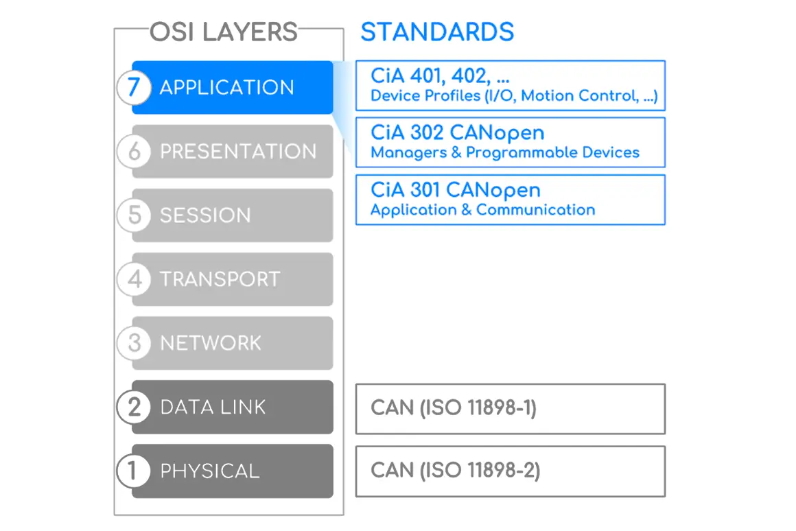
The application layer establishes the communication link to an upper-level application-specific protocol such as the vendor-independent CAN open protocol. This protocol is supported by the international users and manufacturers group, CAN in Automation (CIA).
There are many similar emerging protocols dedicated to particular applications like industrial automation or aviation.
Examples of industry-standard CAN-based protocols are KVASER’s the CAN Kingdom, Allen-Bradley’s Device Net, and Honeywell’s Smart Distributed System (SDS).
Focus Points to Establish a CAN Network
- CAN protocol define the Data Link Layer and part of the Physical Layer in the OSI model.
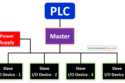
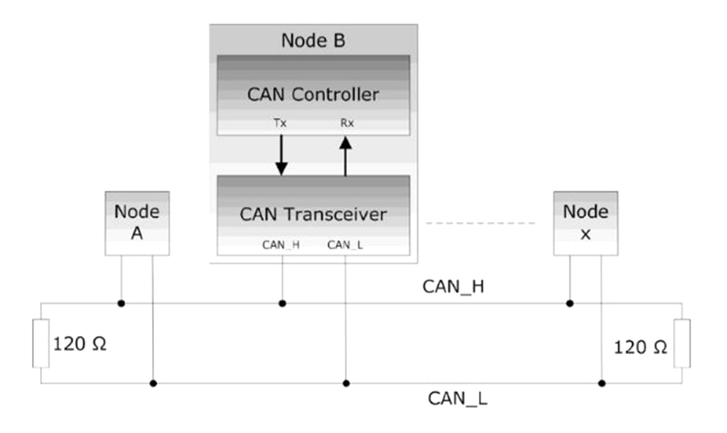
- Each CAN unit connected to the bus can be called a node. All CAN units are connected to a bus terminated at each end with 120 Ω resistors to form a network.
- The CAN bus consists of two wires (CAN_H & CAN_L lines).
- The CAN controller determines the bus level based on the difference in the power level on both wires.
- Bus levels are divided into dominant and recessive levels, which must be one of them, the sender sends the message to the receiver by making a change at the bus level.
- In the dominant state, the voltage of CAN_H is about 3.5V and the voltage of CAN_L is about 1.5V. In the recessive state, the voltage of both lines is around 2.5V.
- The signal is differential which is why CAN derives its robust noise immunity and fault tolerance. A balanced differential signal reduces noise coupling and allows for high signaling rates over twisted-pair cable. The current in each signal line is equal but in the opposite direction and resulting in a field-canceling effect that is key to low noise emissions. The use of balanced differential receivers and twisted-pair cabling enhances the common-mode rejection and high noise immunity of a CAN bus.
Relation Between Speed & Cable Distance
The CAN bus is a bus that connects multiple units at the same time. There is theoretically no limit to the total number of units that can be connected. In practice, however, the number of units that can be connected is limited by the time delay on the bus and the electrical load.
Reduce the speed of communication, increase the number of units that can be connected, and increase the speed of communication, the number of units that can be connected decreases.
The communication distance is inversely related to the communication speed, and the farther the communication distance, the smaller the communication speed. The longer distance can be 1km or more, but the speed is less than 40kps.
Resources
- Introduction to the Controller Area Network (CAN) by Texas Instruments.
- instructables.com/A-Simple-Tutorial-for-CANBUS
If you liked this article, then please subscribe to our YouTube Channel for Electrical, Electronics, Instrumentation, PLC, and SCADA video tutorials.
You can also follow us on Facebook and Twitter to receive daily updates.
Read Next:
- 4-20 mA Transmitter Wiring
- Electrical Earthing Calculations
- Why 24 Volts DC Power Supply?
- Interposing Relay Panel Wiring
- SCADA Software and Comparison