A Move block is one of the very important instructions you can use when coding your PLC, it is also one of the most commonly used instructions.
MOVE Instruction in PLC
You can hardly find a PLC logic where you don’t need to use a Move block somewhere in the logic.
And that is why it is important to understand how the Move block works to avoid some of the common troubles associated with it.
In this article, we will highlight some of these points.
Move block is Not Edge Triggered
When using a Move you should know that a move block is not edge triggered, which means as long as the enable input “EN” has the signal state 1 the move instruction will be executed.
So if you need to only move the value one time at a certain event you need to make sure the EN is only triggered at that event.
The following video shows that concept.
As you see from the video, as long as the enable signal is 1 the IN will constantly be moved to OUT1.
That is not a mistake in itself, you just need to pay attention if whether is the logic you’re aiming for or not. Because if you need to move the information one time only you need to set a trigger for only that needed event.
Move Instruction Works on the BIT level
The Move block only works on the bit level, meaning it moves the Bits representation of the IN memory area to the OUT1 memory area, only the representation not the value inside.
For example: if IN is 01010101 it will be moved to OUT1 with the same representation of BITs regardless of how will it be interpreted in the OUT1 memory.
Why does it matter?
It matters because if the IN and OUT1 are of different data types, that might cause some trouble if you’re not careful.
The following will explain this point.
If IN and OUT1 are of the Same Data Type
This is the best-case scenario because the same data type means the same data interpretation, so no chance of any mix-up.
Also, no memory area is wasted or no lost information.
If IN and OUT1 are of Different Data Types (IN smaller area)
Here is where some mix up could happen if you’re not careful, see the next pictures for more explanation.
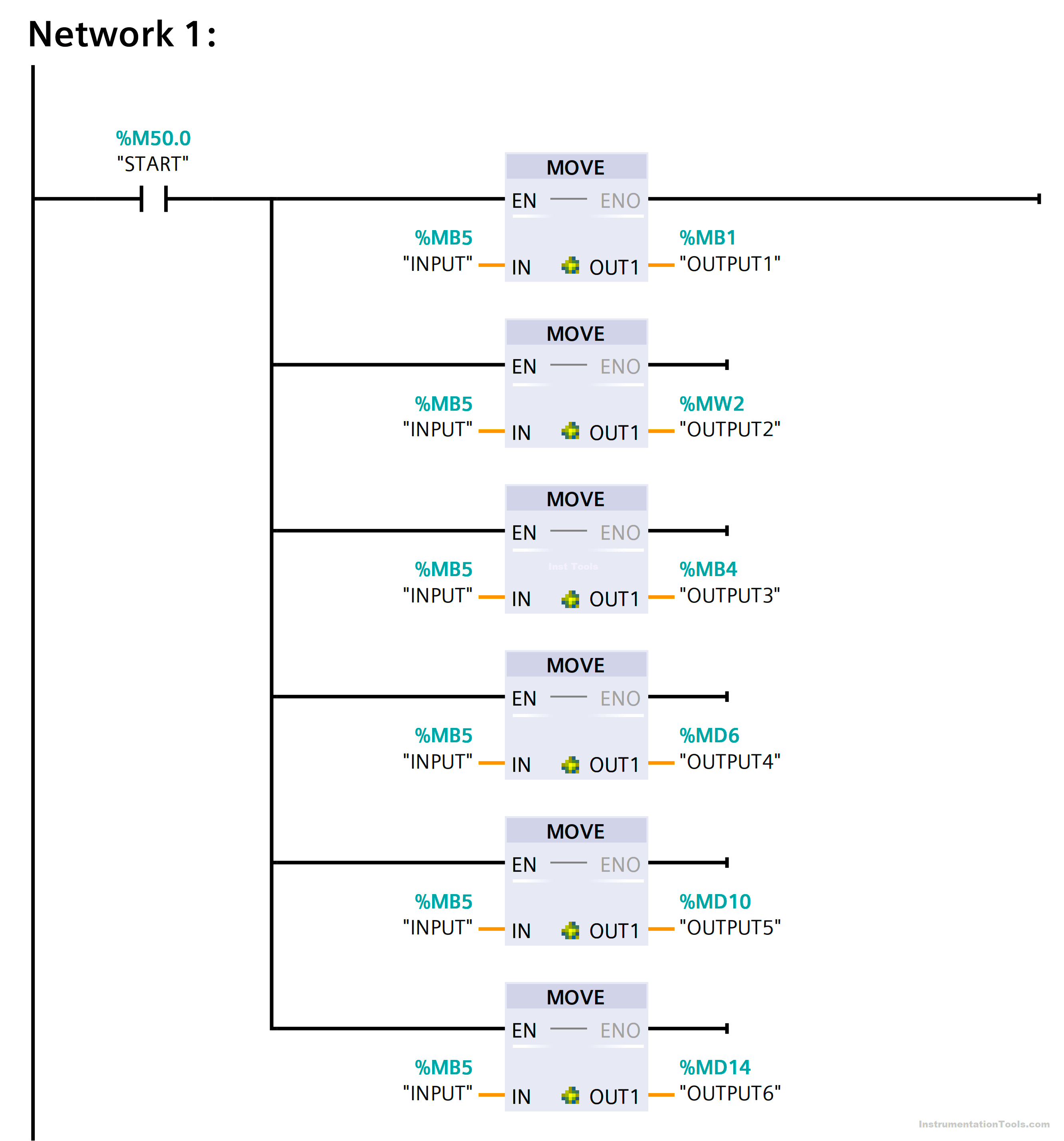
As you see, this is a simple network where INPUT is moved to 6 different outputs from OUTPUT1 to OUTPUT6.
Below is the data type for each one.
| Tag | INPUT | OUTPUT1 | OUTPUT2 | OUTPUT3 | OUTPUT4 | OUTPUT5 | OUTPUT6 |
| Data type | Byte | Byte | Int | SInt | UDInt | UDInt | DInt |
Notice how the outputs have different data types; let’s see how that will affect the outcome. See the next picture 1.
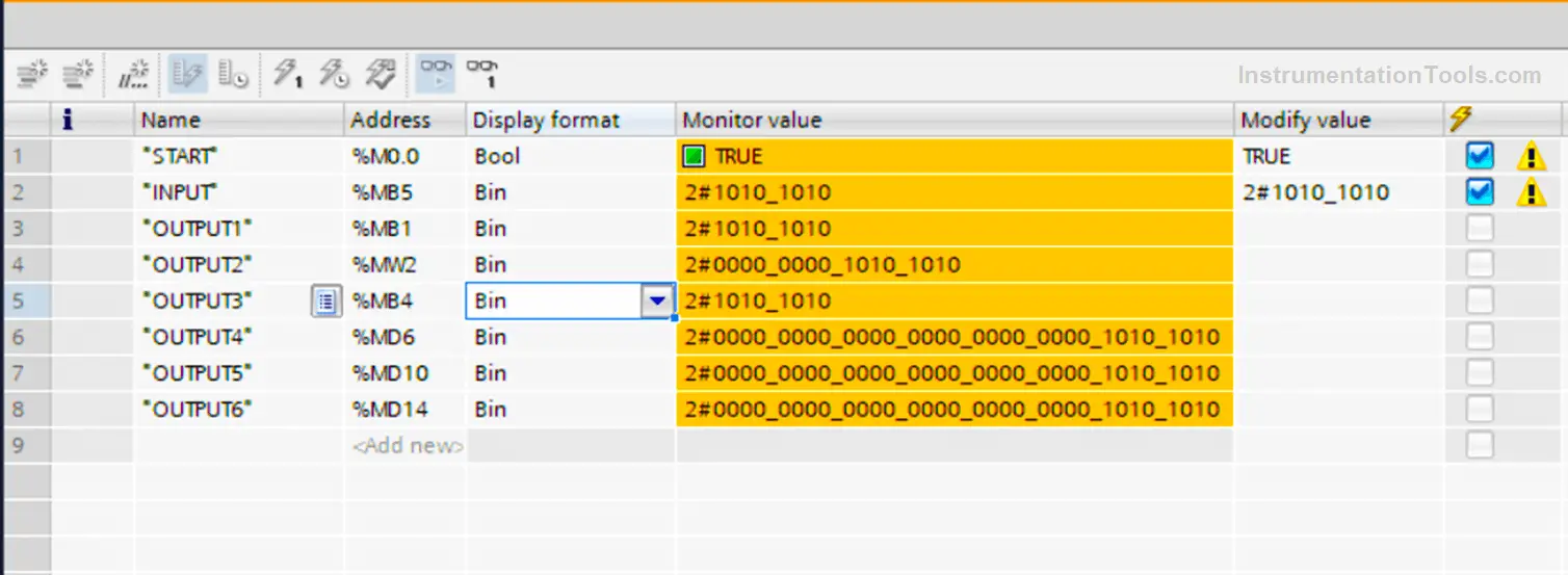
If the INPUT has the Bit representation of 10101010
When the Move instruction is enabled, the Bit representation of the INPUT will be moved to the 6 outputs, but because they are of different data types.
You can see that the input only occupied the same number of bits it has, and the rest of the OUTPUT bits are zeros and never changed.
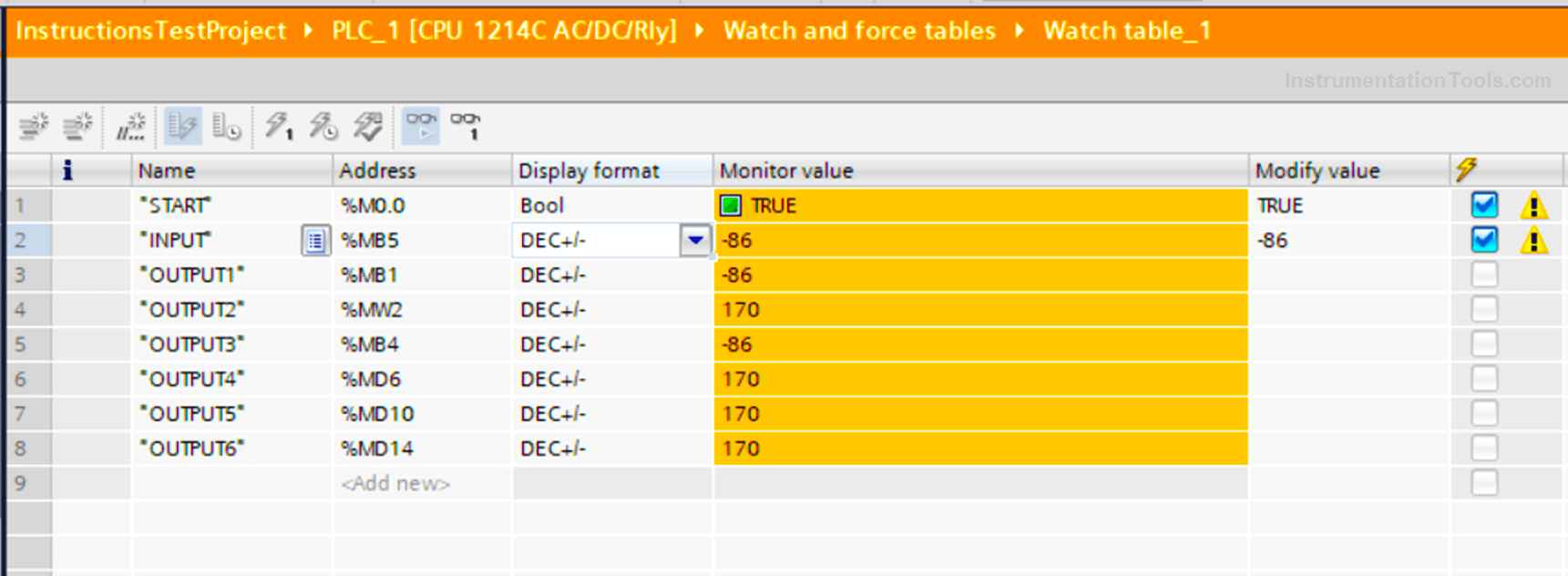
From picture 2 you can see that the value of the INPUT which is -86 is not the same in some of the OUTPUTS.
You can see that the OUTPUT2 value is 170 and not -86, that is because the OUTPUT2 is of data type Int which uses 16-bit memory, and the INPUT is a Byte, represented by only 8 bits.
So when you move 8 bits into an area of 16 bits, only 8 bits of this Int data type will be affected, and the rest won’t be changed. And that is why OUTPUT2 will be of value 170 and not -86.
Because 10101010 is not the same as 0000000010101010
The same with OUTPUT4 and OUTPUT6.
So, when you move a small quantity of data/information into larger areas you may:
- Loss the unused area of the larger memory, and in big projects, you need every bit of memory wisely used to avoid slowing your processing time or buying additional parts.
- You might get the wrong values moved because of different interpretations of bits for different data types, especially when working with signed (+/-) values.
If IN and OUT1 are of Different Data Types (IN larger area)
As you see from picture 3, the IN area is now larger than some of the OUTPUTs
The following table shows data types:
| Tag | INPUT | OUTPUT1 | OUTPUT2 | OUTPUT3 | OUTPUT4 | OUTPUT5 | OUTPUT6 |
| Data type | Dint | Byte | Int | SInt | UDInt | UDInt | DInt |
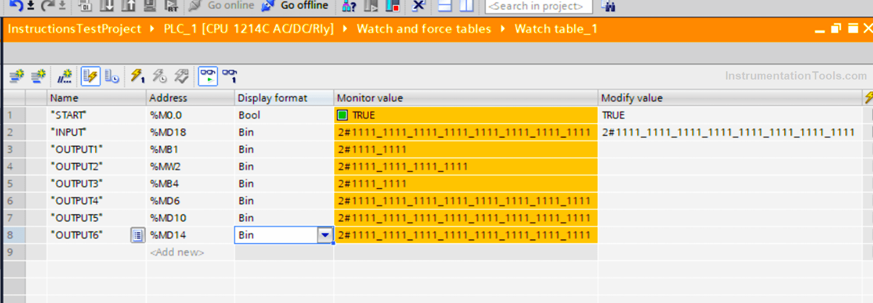
The value of the INPUT is 4_294_967_295 which is the highest value this data type can hold, it means as you can see in picture 3, the bit representation will be all ones 1111_1111_1111_1111_1111_1111_1111_1111
When you try to move all those Ones into a smaller memory area, you are bound to lose some of the data, because there is simply not enough space in a Byte or an Int to hold all information in a DInt and that is why you would expect, the values in these OUTPUTs will be different. As shown in the next Picture.
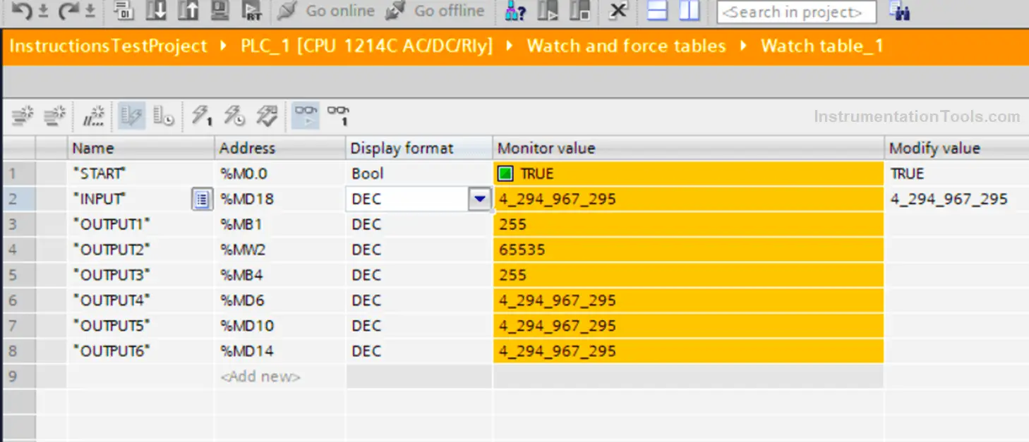
As you can see in picture 4 as expected the values inside different OUTPUTs are different. Because of different interpretations of each data type to the information it holds.
How to Avoid this Problem in Move Instruction?
First, you need to know that it is not a problem per say, if you’re paying attention to the data types you are using, and if you know what you should expect from your logic.
But it is also worth mentioning that all of this mix-up is a possibility if you’re not using the IEC check when working with your code _ by the way, not using the IEC check is the standard configuration in TIA Portal_.
If you’re using the IEC check, then the system will make sure the IN and OUT of the MOVE block are compatible together and it will give you a warning if you use data types that are not compatible. See pic.5 and pic.6
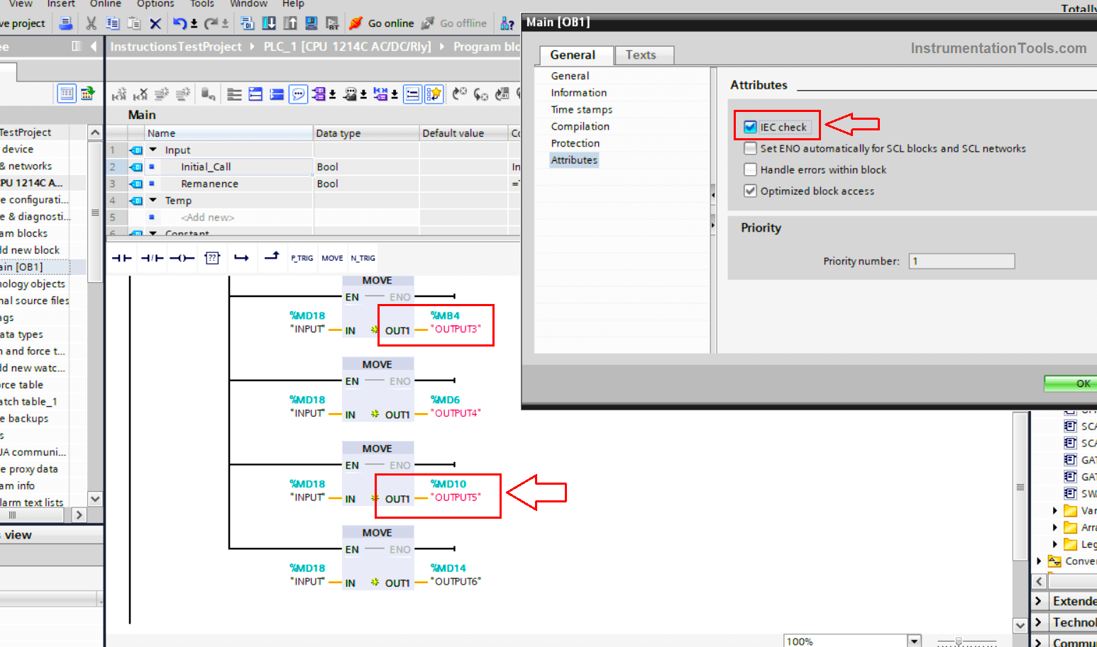
See in picture 5, when the IEC is checked, the system gave you a warning that outputs 3, 4, and 5 are not compatible and it will force you to choose the correct data type.
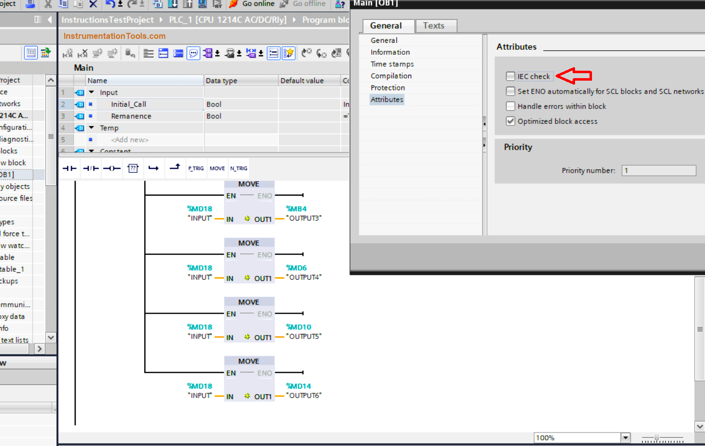
As you can see in picture 6, when the IEC check was not chosen, the system didn’t care about compatibility between IN and OUT and will almost accept any data type you choose.
You can check the help of MOVE instructions in Siemens TIA Portal to find a list of compatibility with/without the IEC check.
Learn the basic programming related to the MOVE block from the below video.
Conclusion
- Move Block is not edge triggered.
- You should pay attention to the data type of IN and OUT when using the MOVE block.
- You can avoid this mix-up possibility if you choose the IEC check.
- You can choose to work with different data types if that is what you want, but in most cases, you’ll be losing some memory areas unused or losing some of the information moved to the new OUT area.
If you liked this article, then please subscribe to our YouTube Channel for Instrumentation, Electrical, PLC, and SCADA video tutorials.
You can also follow us on Facebook and Twitter to receive daily updates.
Read Next:
- SCADA Indusoft Web Studio
- PLC Programming Languages
- How to Design an Effective HMI?
- Inputs and Outputs in Delta PLC
- Logic Gate Functional Block Diagram