In this article, we will talk about one very useful tool you should know and use when designing HMI visualization for your automation process. That is the Faceplate.
Contents:
- What are Faceplates?
- Why are they useful?
- How to create and edit a Faceplate?
- Faceplate Properties.
- Conclusions.
What are Faceplates?
To understand what a Faceplate is, let’s remember what a Function is. As we discussed before a function FC or a function block FB are blocks of code that can be used multiple times in your project.
You first create the FC or FB using generic/unassigned inputs and outputs and each time you need to use the FC or the FB you just call it in your program and give it the related assigned inputs and outputs. That way you save the time and effort you would need to create the same logic over and over again.
Another example is the UDTs we talked about in previous articles. When you have a process that has multiple numbers of the same sub-system, instead of declaring the same tags for each system individually which will take time and effort and things might get confusing along the way, you just create a UDT that carries all the related information for that sub-system. And each time you need this information you would just use the UDT.
A Faceplate is simply the same concept as UDTs, FCs, and FBs but for the HMI visualization part.
Imagine if you have a process that has 30 Tanks sub-system, 25 Pumps sub-system, and 15 motors sub-system, and you need of course to make HMI visualization for your entire process to control each element individually. The normal approach would be to create the visualization for each element one by one, but this would take a lot of time and effort. And they are all basically the same. A Faceplate approach steps in to make this visualization easier and faster.
A Faceplate is a standardized picture object that you create centrally as a type in a project to represent the visualization of a specific sub-process, or sub-system in your larger project. This is particularly useful when you have multiple numbers of the same sub-system in your PLC project as you would create the visualization of that sub-system just one time and only call the Faceplate each time you need it in your visualization.
So in our previous example where we have 30 tanks, 25 pumps, and 15 motors we would just create a Faceplate for each item and reuse it for as many times as we need.
So our design procedure is reduced to only 3 Faceplates one for the tanks, one for the pumps, and one for the motors.
Why are Faceplates Useful?
Using a Faceplate will reduce the time and effort consumed to design the same thing over and over multiple times.
If in case you need to modify your visualization, you can make this modification to your Centralize Faceplate and the change will be updated to elements automatically. Without Faceplates you would have to make this modification to all the elements individually.
How to Create a Faceplate?
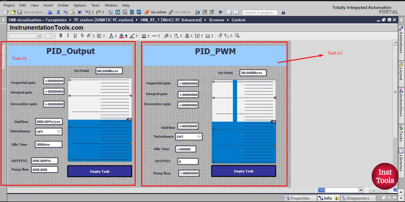
We will the same Tank simulator project we used for the PIDs articles; in this project, we had multiple Tanks that were to be controlled with PID blocks to maintain the level of the tank at a given set point.
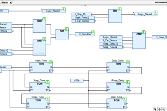
We simulated two tanks in our last article. See picture 1.
Picture 1. Old simulation of 2 tanks.
As you can see, for the visualization of the two tanks we had to build everything from the beginning for the second tank. If we need to add another tank we would have to rebuild the visualization all over again for this tank. We can avoid all of this by using the concept of faceplates.
Using faceplates, we just need to create the visualization we want for our sub-system (Tank) one time. For this article, we will not use all the elements we used before n our simulation.
We will create a simple visualization that only shows the Tank level, set point, Outflow, and the empty tank push button. And we will build our faceplate from this block of elements. See picture 2.
picture 2. Create a simple tank visualization.
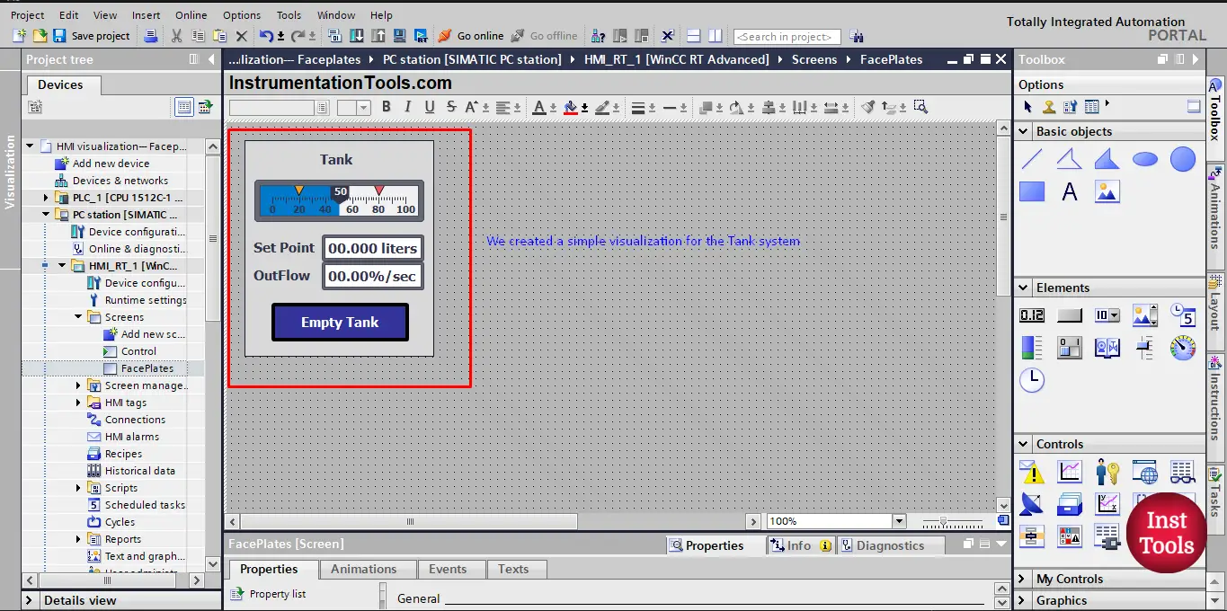
To create a faceplate from this visualization, you just select all the elements of the visualization together and then right-click, and then click on the create faceplate option. See picture 3.
Picture 3. Create faceplate.
When you click on the create faceplate option, an add type window will pop up asking you for some information before creating the faceplate, like the name of the faceplate, the version number, and some comments if you want to.
Try to give your nameplate a proper name that reflects its purpose, in our case we named it Tank. Then press OK. See picture 4.
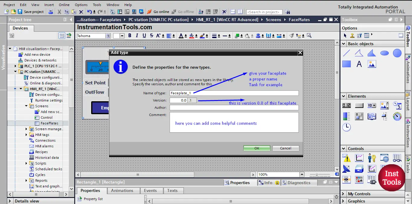
picture 4. Add type window.
When you press OK, a faceplate with the name you chose will be created and the library view will open on the new type (faceplate) you just created. See picture 5.
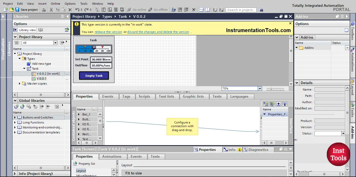
picture 5. Library view.
In this library view, you can make changes to your faceplate, you can add or remove new elements to the faceplate, and you can also set the different properties of your faceplate. See picture 6.
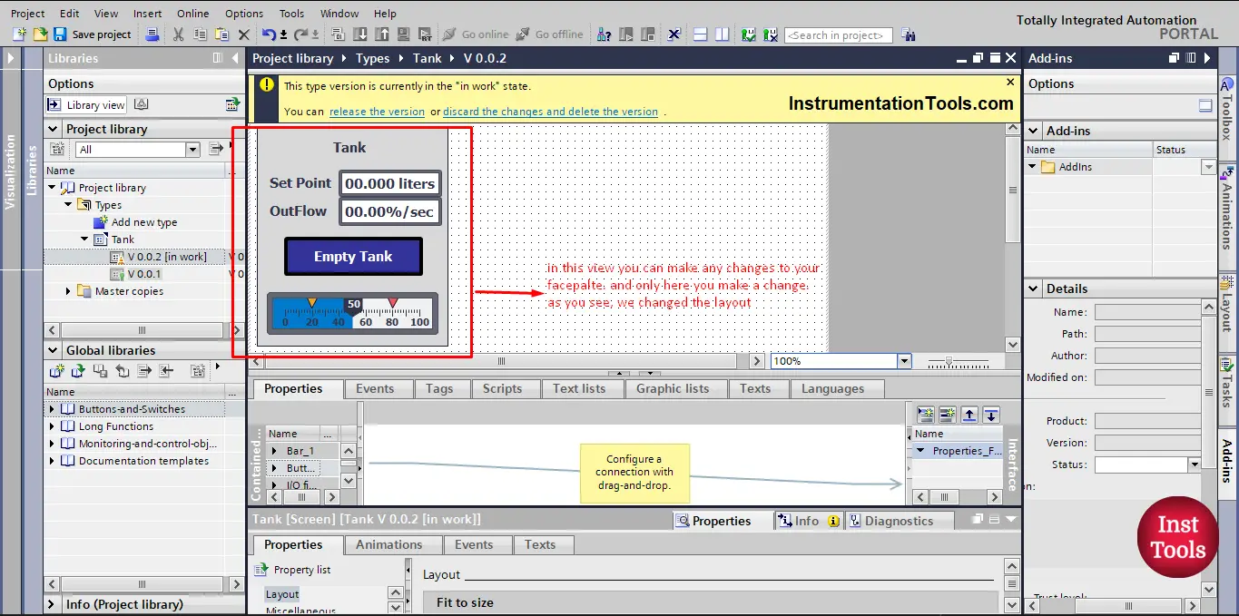
picture 6. Make changes to your faceplate in the library view.
As you see in the picture, we changed the layout of the faceplate, so now, the set point and the outflow are at the top of the faceplate, the tank level is at the bottom of the faceplate and the empty tank button is in the middle.
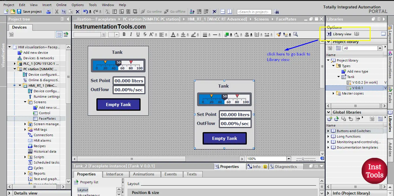
So obviously we made some changes. If you go back to the normal visualization view, you will see the faceplate is the same and the changes we made are not applied. See picture 7.
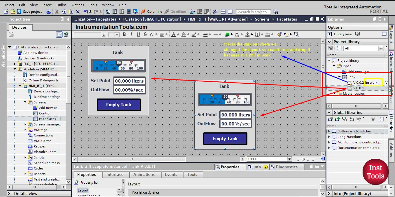
picture 7. The Faceplate new version is still in work.
The reason why no changes were applied, is that our faceplate version is still in work, meaning we haven’t yet confirmed to release the version of the faceplate. Think of it like a mobile app, each time a new feature is created a newer version of the software is released.
So we have to release the version to apply the changes we made. We release the faceplate version by going back to the library view. See picture 8.
picture 8. Go back to the library view.
In the library view, you can both release the version to apply changes to the faceplate or discard the changes and delete the version. See picture 9.
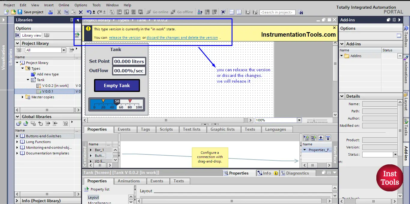
picture 9. Release the version to apply changes.
Once you press to release the version, a Release type version pop-up window will appear and it will give you some options for releasing the version. See picture 10.
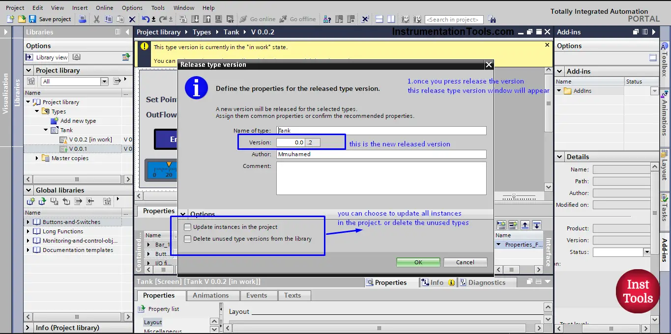
picture 10. Release type version window.
As you can see, you have the option to update all faceplate instances in the project, and you can also delete the unused versions from the project.
We will just press OK to release the version. And then we go back to the visualization view. See picture 11.
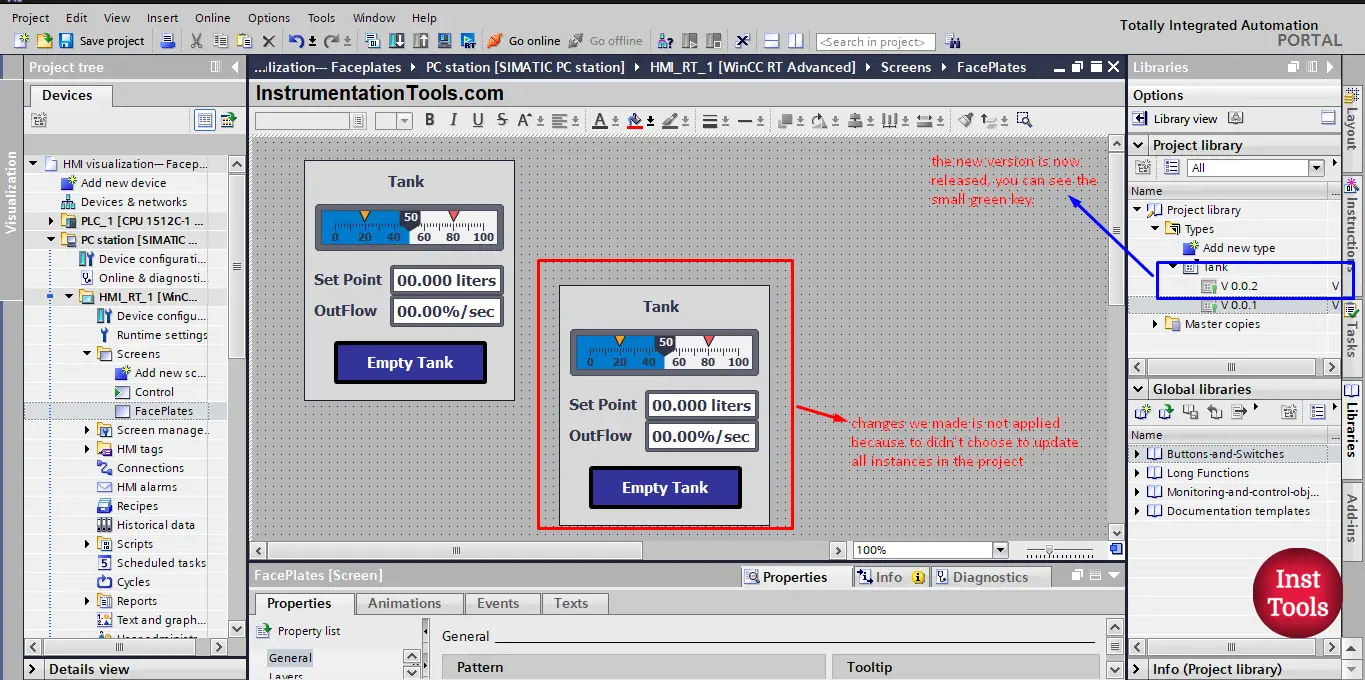
picture 11. The new version has been released.
We can notice two things from the picture:
- The new version is now released, you can see the small green key next to version V0.0.2, and also the (in work) is no longer written next to the version.
- The old faceplate instances are not updated with the changes of the new version and that is because we didn’t choose that option in the previous Release type version window.
Now, if you try to add a new instance to your PLC project it will be added with the changes that were made. However, the old instances are not yet updated. To update all instances in the project, you just right-click on the Tank type in the project library and choose update types. See picture 12.
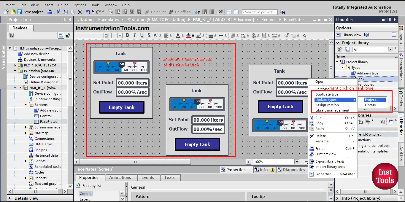
picture 12. Update types.
This will open another window, the Update types in the project pop-up window where you can choose the project to update its types. We will choose our HMI project. And then click OK. See picture 13.
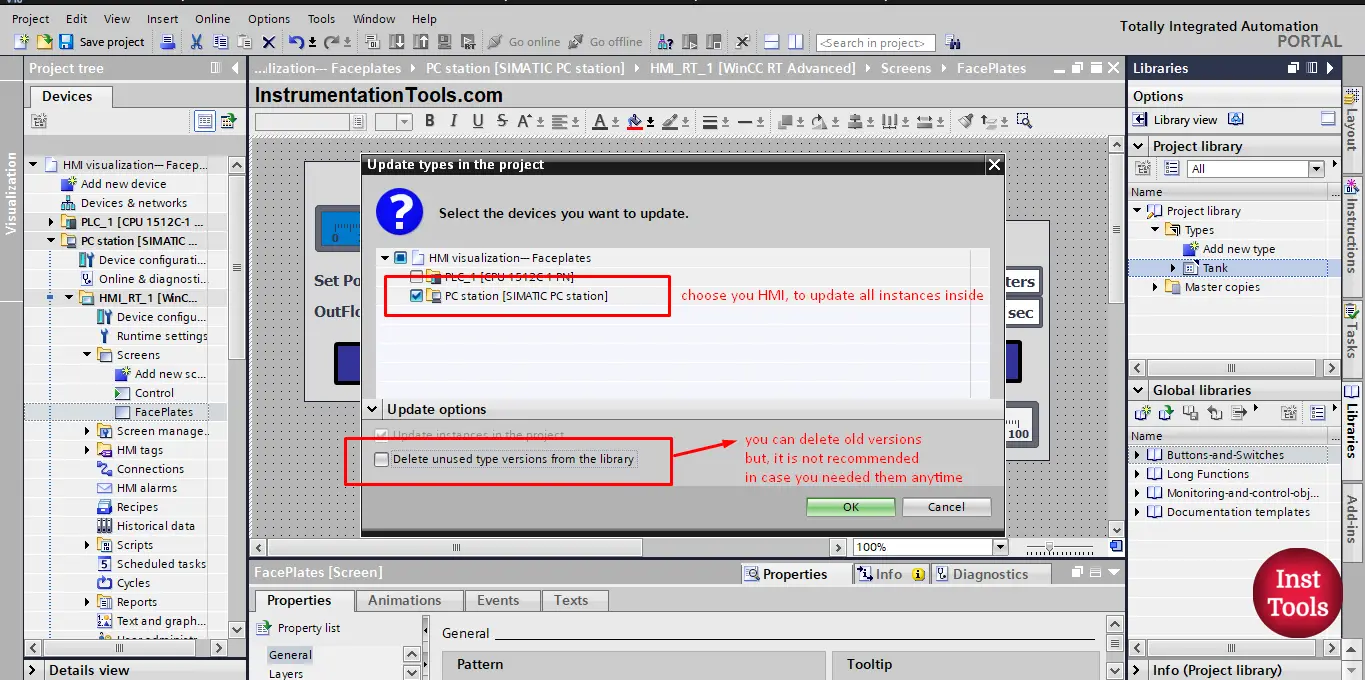
picture 13. Press OK to update all instances.
Once you press OK, the changes to the new version will be automatically updated to all instances in the project. See picture 14. Notice how the old versions of the faceplate are now updated with the new layout.
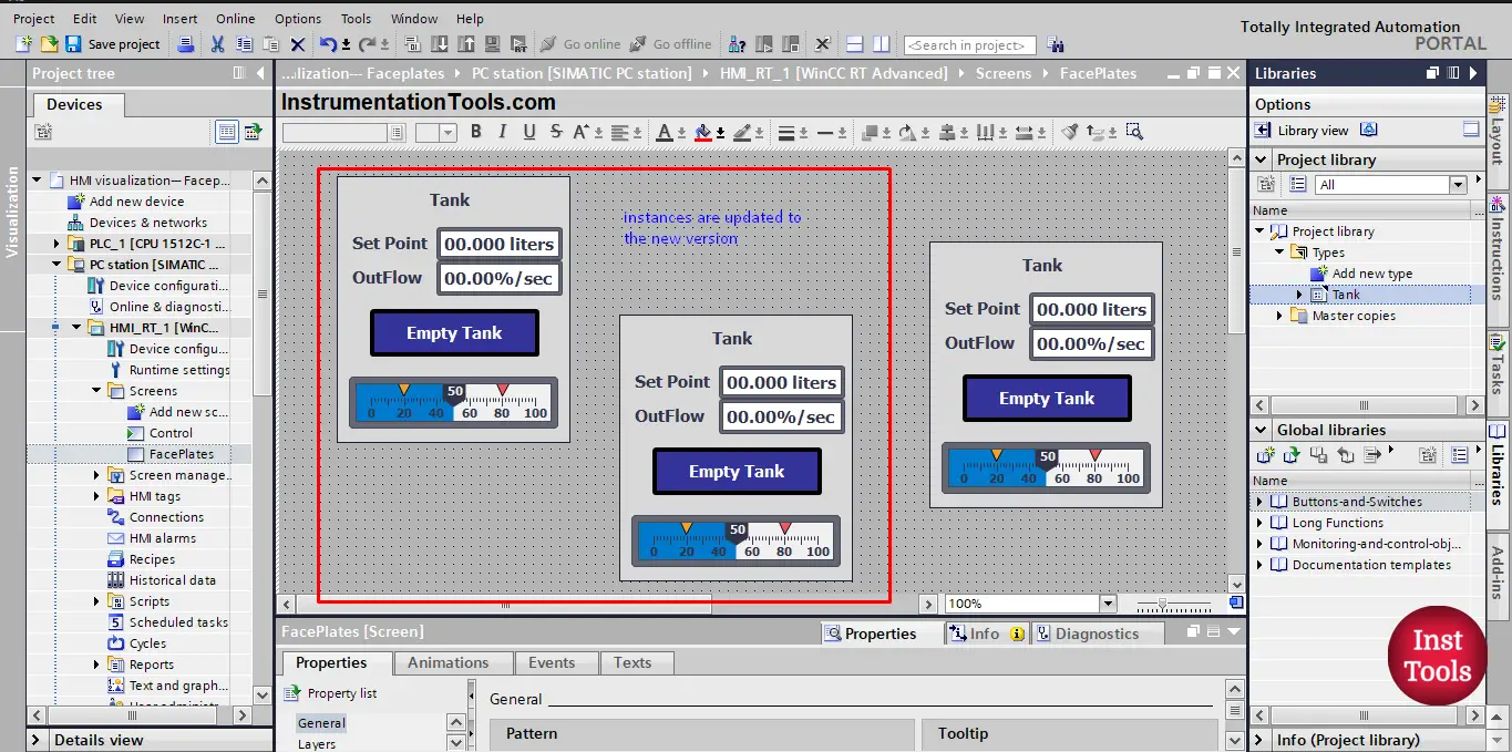
picture 14. Instances are now updated.
So, we created a faceplate and we used faceplates for 3 different tanks as you can see from the picture, we now need to connect each faceplate to each related tank. To do so, we have to set up an interface between the faceplate and the outside PLC project. This is done in two steps:
- Defining the needed properties of the faceplate.
- Connecting the properties to project actual tags.
In this article, we show how to add properties of the faceplate and the connection with the PLC tag will be shown in another article.
Faceplates Properties
If you click on any one of the faceplates you have, you will find the interface section in the properties of the block is empty, because no properties are set up yet. See picture 15.
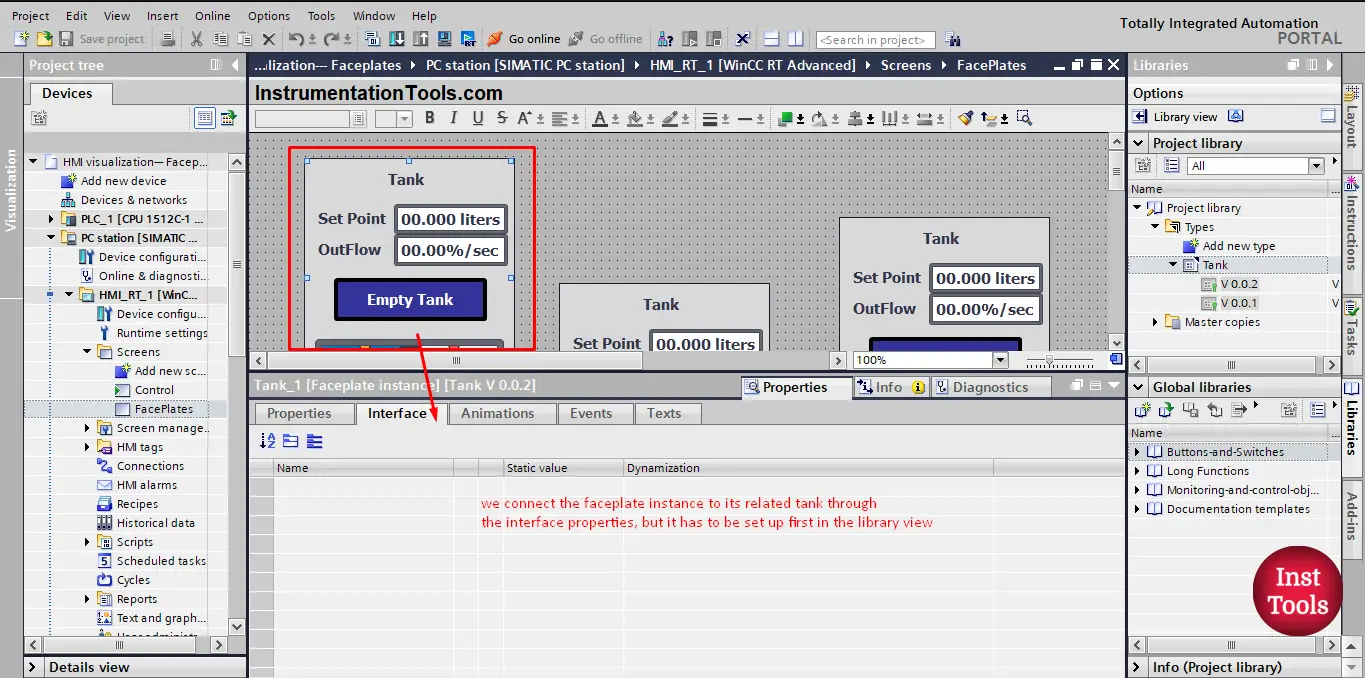
picture 15. Faceplate interface.
We connect the faceplate to its related tank through the interface properties, but it has to be setup first in the library view. To do so, just right-click on the faceplate and press edit faceplate. See picture 16.
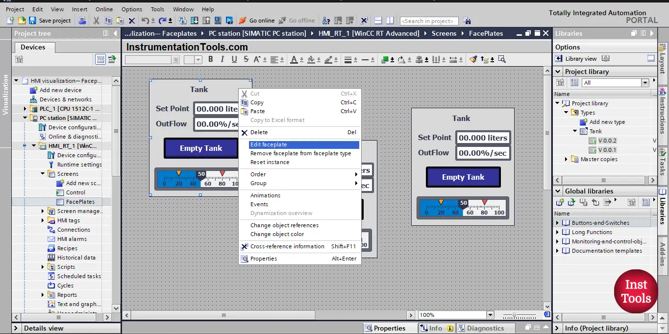
picture 16. Edit faceplate.
This will open the library view and create a new in-work version. You can start adding properties in the middle area of the library view. See picture 17.
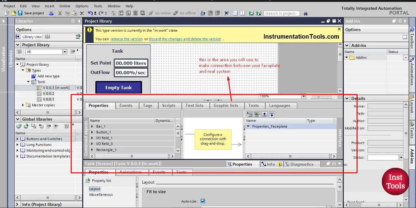
picture 17. Properties area.
This area is used to define properties for the faceplate and make connections between these properties and the real project. To add a property you just click on the add new property button. See picture 18.
picture 18. Adding properties to your faceplate.
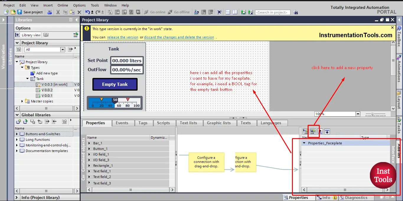
Our faceplate has 4 main elements and they are the set point, outflow, tank fill level, and the empty tank button. We need to add a property for each element to be able to connect with our project.
So we just click add a new property and give the property a proper name and proper data type. See picture 19.
picture 19. Add all needed properties.
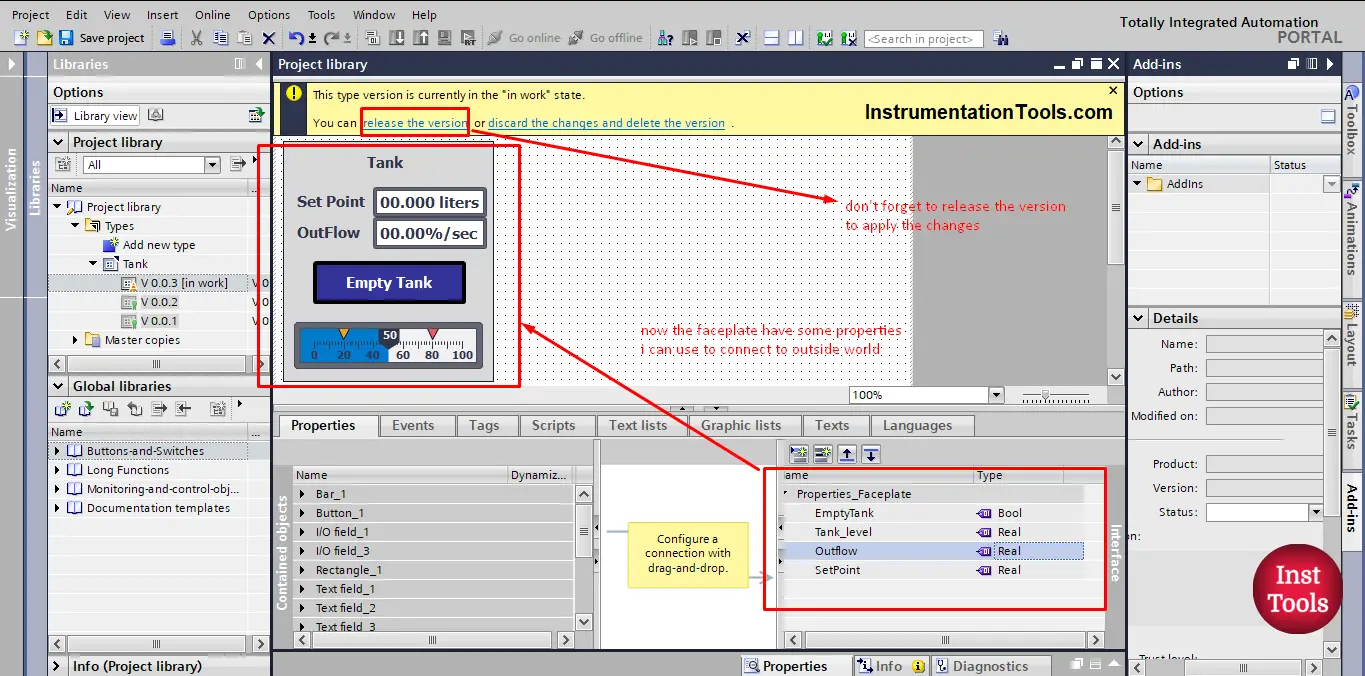
You should pay good attention towards the data type of the property you add, it has to be the same as the parameter of the actual project that it will connect to.
For example, the tank fill level in the PLC project is of data type Real, so the property “Tank_level” should also be Real. After you finish adding all the needed properties, don’t forget to release the version to apply the changes.
Now, if you click on the faceplate instance you can see all the properties set up for the faceplate. You can connect these properties to your PLC project. See picture 20.
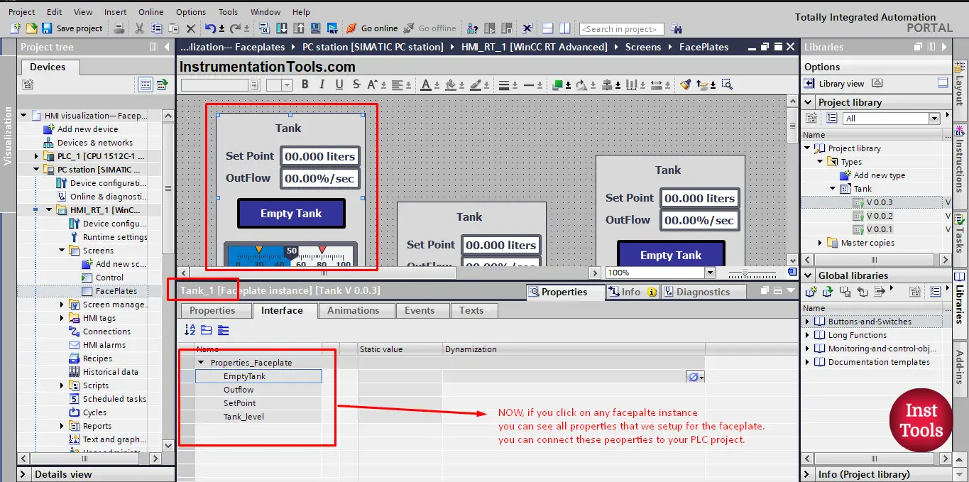
picture 20. Properties of faceplate interface.
We now finished creating our faceplate. And as we mentioned before we can use this faceplate as many times as we want and we don’t need to create visualization for the tank from the beginning.
If we want to simulate the 15 tanks we have in our project, it will be very easy to just drag and drop the faceplate into your HMI screen. See picture 21.
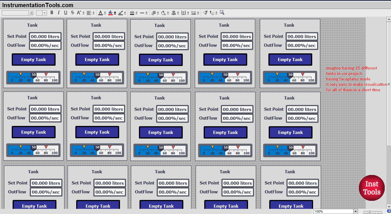
picture 21. Simulating 15 different tanks.
Download: Faceplate Document
Conclusion
- Faceplates are very useful when you have multiple numbers of the same system.
- Using faceplates will reduce the time and effort to add new items.
- We have to set up interface properties for the faceplate to be able to connect with your PLC project.
If you liked this article, then please subscribe to our YouTube Channel for Instrumentation, Electrical, PLC, and SCADA video tutorials.
You can also follow us on Facebook and Twitter to receive daily updates.
Read Next:
- PLC PID Controller Output Types
- Static and Temp Variables in PLC
- Power Supply Sizing for Systems
- How to Read the PLC Datasheet?
- Update the Firmware Version of PLC