The basic structure of programmable logic controller (PLC) design can be classified into two parts.
- PLC hardware and
- PLC Software.
PLC Hardware
PLC hardware parts consist of
- Central processing unit (CPU),
- Input/ Output Modules,
- Communication port,
- Programming device and
- Power supply.
PLC Software
PLC software is a programming application for writing logic.
When it comes to PLC hardware, we can classify them into two different types.
- Open architecture and
- Close architecture.
Most of the PLC controllers are proprietary, which means procurement of hardware should be very compatible with each other.
For example, Siemens PLC CPU hardware should compatible with only Siemens IO modules. If the controller is open type architecture means, you can mix or use different vendor products together.
If you explore different PLCs, you can find more similarities and very few differences like the working environment of PLC software, addressing of Inputs & Outputs, and hardware structure.
Program in one controller cannot be used for another manufacturer controller, obviously, the logic of the program can be the same but the wiring method will be different.
The instructions and programming software will also change as per the vendor-designed PLC software.
Also Read: Introduction to PLC
Important Parts of PLC
- Central Processing unit
- Power supply
- Input-Output Modules
- Programming Device
Central Processing Unit (CPU)
Processing unit (CPU) is the brain of the PLC system. The function of the CPU is to execute the logic we have downloaded into it.
While executing the logic, PLC control all the IO modules connected with the CPU as per the user-written program.
The memory unit is used in the CPU for storing the PLC program and other data involving for monitoring and controlling the industrial system.
PLC is usually recommended for repetitive processes, which means it will repeat scanning the process (IO’s) again and again. It is called SCAN TIME.
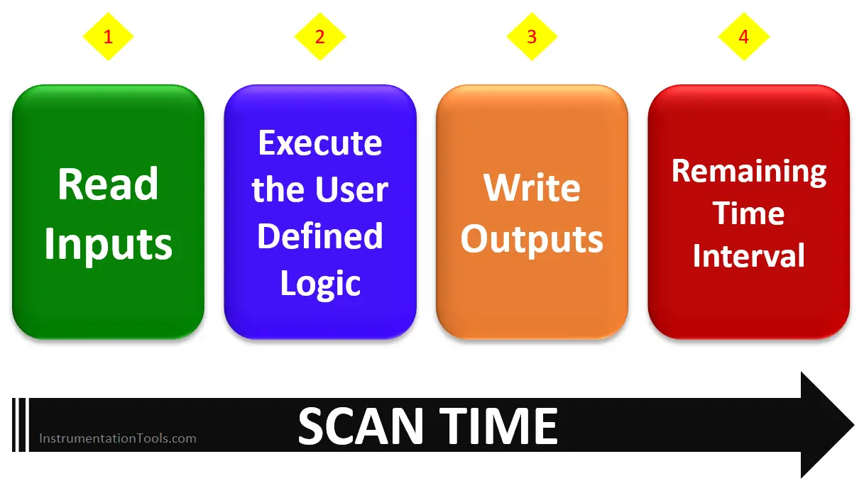
When PLC is in run mode, it will start with Reading of Input status, then fetch the details into the program, and update the outputs accordingly.
PLCs also monitor and check the software status, hardware modules’ healthiness status, and process plant status, and updates these data to the users. This diagnostic information is very useful to check if any error is raised or not.
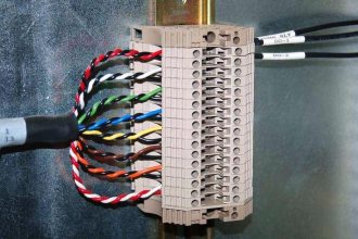
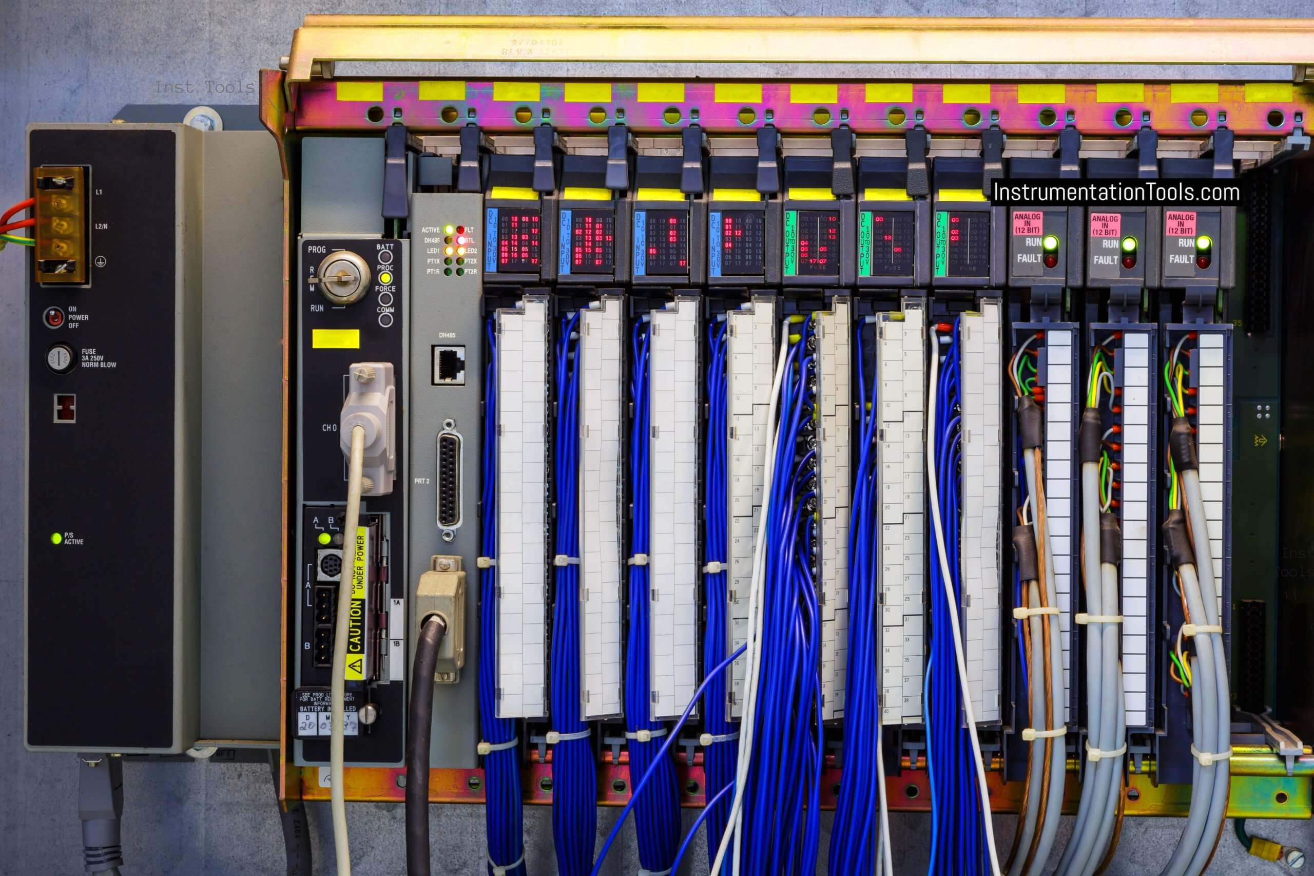
Input and Output Modules
IO modules are common to all PLC types, which are used to make communication between CPU and field devices.
If you want to run a motor using a switch means, we have to classify which devices are come under the input and output list.
In the mentioned example, the switch will be the input device and the motor is the output device.
To run a motor using switches with the help of relays, we need to do wiring directly between the switches and motor using the required relays. So the wired connection will be called a relay concept but in PLC we are not going to make a direct connection between switches and motor.
The switch will be connected to the input module of PLC and the Motor is connected to the output module of PLC.
We have to write a ladder logic by using the respective address of the switch and motor. As per the PLC logic, we can START and STOP the motor using the switches.
Sometimes due to any faults, or due to short or open circuits in the field, the input and output modules will be damaged. As we connect these IO modules to the CPU, the CPU also may get damaged.
So it is always recommended to use optical isolators between the IO modules and field devices. These isolators will be installed in the PLC cabinet in the control room.
We have two different classifications of IO modules
- Fixed IO Module and
- Modular IO module.
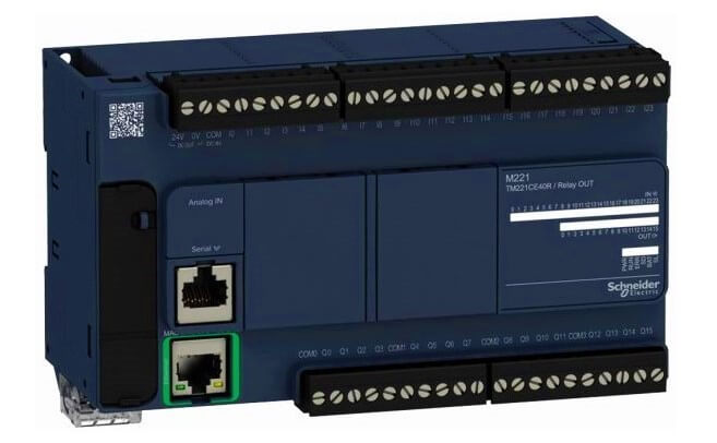
Fixed IO Module
Fixed or compact module types will be having IO modules designed with CPU.
In One rectangular box (device), we will be having all components of PLC except the Programming device.
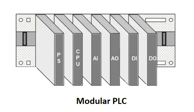
Modular IO module
Modular Type is nothing but a single module for each “n” number of IOs.
If we need 6 number of Analog input signals then we have to use a standard 8 channel or 16 channel or 32 channel AI module.
Similarly, If we want to connect 20 digital input signals to the PLC then we need a 32 channel DI module in the PLC.
Power supply will be one module, CPU will be another separate module, different input, and output modules. If we have redundancy in the PLC then extra modules will be required.
These modules are plugged into the rack or cabinet-like structure to make communicate with each other.
Power Supply
PLC needs 24 volts DC supply for its operation. Some PLCs work with 230 volts AC supply.
The power supply details of PLC depend on the type of PLC model, manufacturer of PLC, or as per the geographic location and standards.
For IO modules, we need a separate power supply for its operation. Some micro PLC types can able to supply power for their modules.
But in a larger PLC system, we have to give a separate power supply for its operation.
In fixed or compact type PLC, we can connect the power supply to the inbuilt positive and negative terminals.
In modular type PLC, power supply modules are provided with each rack unit where CPU, IO modules, and any other modules will be installed. This power supply module will take care of the requirements of power for that rack unit.
Also Read: PLC Training Courses
Programming Device
In a relay control system, we used to wire the circuit using hardwires for making the application/logic whereas, in PLC, we have software for doing the same but without hardwires.
We have different PLC languages which will be used for building the logic behind the application.
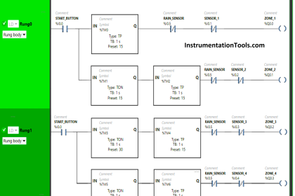
There are five languages for writing the PLC program, in that ladder logic is mostly using one in the control industry.
In ladder logic, there is no need of writing codes or words instead we use graphical symbols for implementing the application logic.
If you know relay logic then it’s very easy to write ladder logic. Nowadays we are using computers and laptops installed with PLC programming software. So here programming devices are our computers and laptops.
But in the olden days, handheld devices are used for programming the PLC. The handheld device will be having small buttons which are used to write a logic by connecting the device with PLC.
Programming tools are not only used for uploading or downloading the program, we can able to monitor the inputs and outputs status while PLC is in run mode.
We have to design our required logic using the available instructions in the PLC software. These instructions and symbols are referenced from international standards.
Once our PLC logic design was completed, we have to download this code into the PLC CPU. So we have to connect a cable between our laptop or PC with the CPU.
Then we can initiate the download function then the PLC logic will be stored inside the memory of the CPU. Next CPU can read the memory and executes as per the logic.
We can also copy the logic inside the PLC CPU to our laptop or computer. This is called uploading the program from PLC to a computer or programming device.
If we have any faults in the PLC software or hardware or in the field then we can easily troubleshoot by going online in the PLC software and monitor the running program code and do the testing for identifying the problems.
Author: Hema Sundaresan
If you liked this article, then please subscribe to our YouTube Channel for PLC and SCADA video tutorials.
You can also follow us on Facebook and Twitter to receive daily updates.
Read Next: