In the previous article, we talked about how to add a PID block to your TIA Portal project, we also talked about how to configure and auto-tune your PID in TIA Portal. In our simulation example, we set our program so that we can use the Output_PER. In this article, we will use the PWM output of the PID and show the difference in PID controller behavior between the two types of outputs.
Contents:
- Explaining our simulation Project.
- Defining new tags for TANK 2.
- Coding analog inputs of TANK 2.
- Coding analog output of TANK 2.
- TANK 2 simulator function block.
- Adding and configuring the PID block for TANK 2.
- Explain the HMI visualization.
- Auto-tune the PID block.
- Comparison view of the two PID blocks.
PID Controller Output Types
We have been using the same Tank system for the previous few articles, we will continue to use the same tank system for this article, however, we will add another tank system to be able to compare the two systems’ behavior with the different PID blocks, so we can understand how the PID works with each output type.
The TANK 2 system will be almost exactly the same as the original tank system, except for two main things and they are:
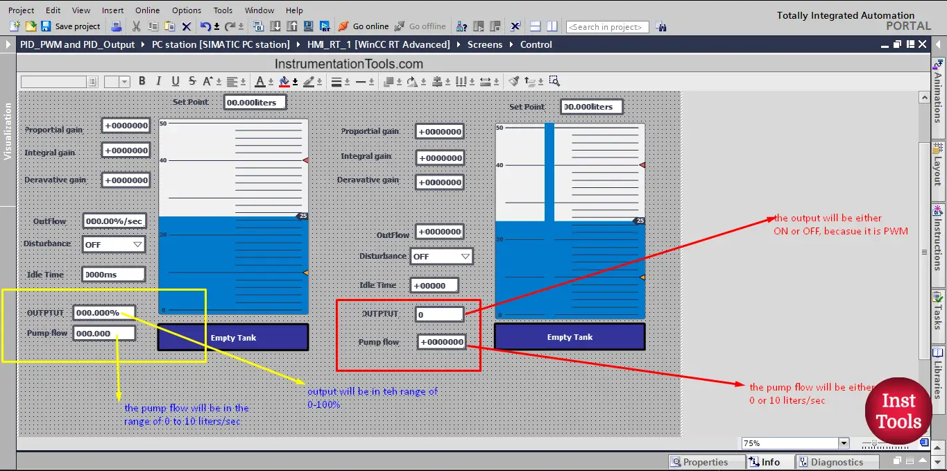
- The pump of the tank 2 system will work in an ON/OFF manner, meaning it will be either ON or OFF, because we will use the output_PWM of the PID.
- The pump flow will not be a range of 0-10 liters/sec, it will have a constant flow of 10 liters/sec when it is ON and 0 liters/sec when it is OFF.
The rest of the tank 2 system will be the same as the original tank system.
Define new tags of the TANK 2 system
As we have a new tank, the new one should have new inputs and outputs for the sake of simulation. See picture 2 for defining the new analog input of the tank 2 fill level.
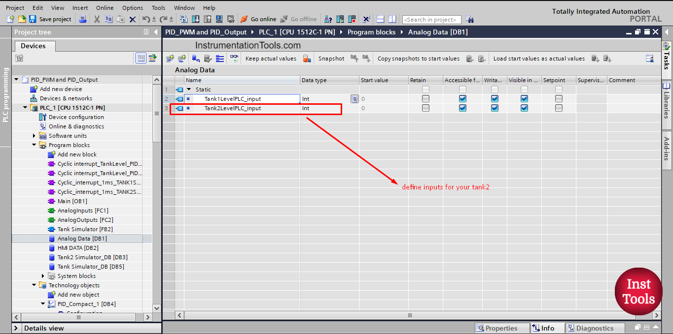
Picture 1. Define tank2 analog input
Next, we need to also define the tags that will be used by the HMI for the simulation of the system. See picture 2.
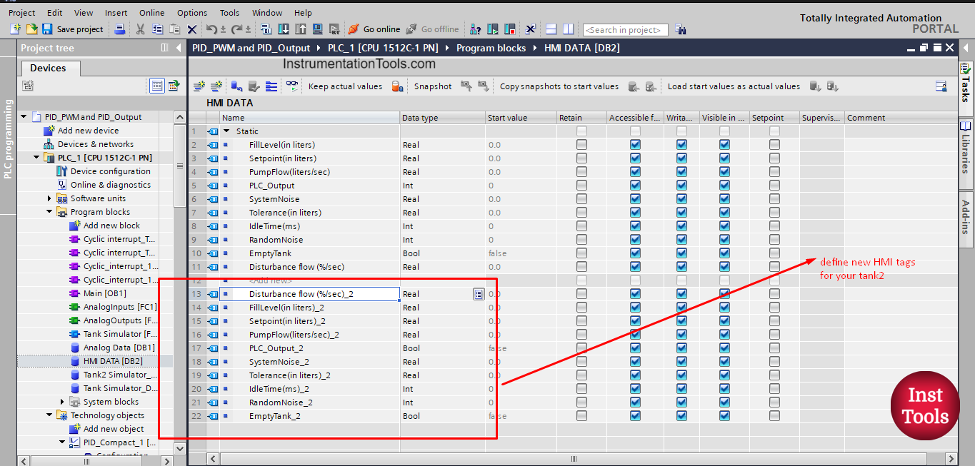
picture 2. Define new HMI tags for your tank2
did you notice, the new tags are exactly the same as the originals, we just added an indication that they are defined for tank 2.
So if we have 10 tanks in our process we will need to define the same parameters 10 times. This can be a very tedious and time-consuming task.
Coding analog inputs of TANK 2
Remember when we talked about functions and function blocks, and how they can be reusable if they are well designed with this aspect in consideration? Anyway, we already created a generic function for the analog input of a tank system and we called it before for our tank 1 system, now we just need to call it another time but for tank 2.
See picture 3 shows different calling of the analog input function for the tank 1 and tank 2 systems.
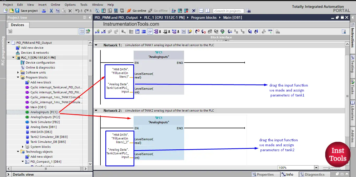
picture 3. Reusability of the function Analog Inputs.
To call the function, you just drag and drop your function in the main OB1 and assign the proper parameters for each tank. You will notice from the picture that the function is the same but the parameters are different and that will give the handling of two different tanks analog inputs.
Coding analog output of TANK 2
For tank 2, the pump output here will not be an analog output, this output will come from the PID_PWM output and it will be a Boolean output, meaning it will be ON or OFF. So we won’t need to use the analog output function we created before for Tank 1. See picture 4 for coding the pump output of tank 2.
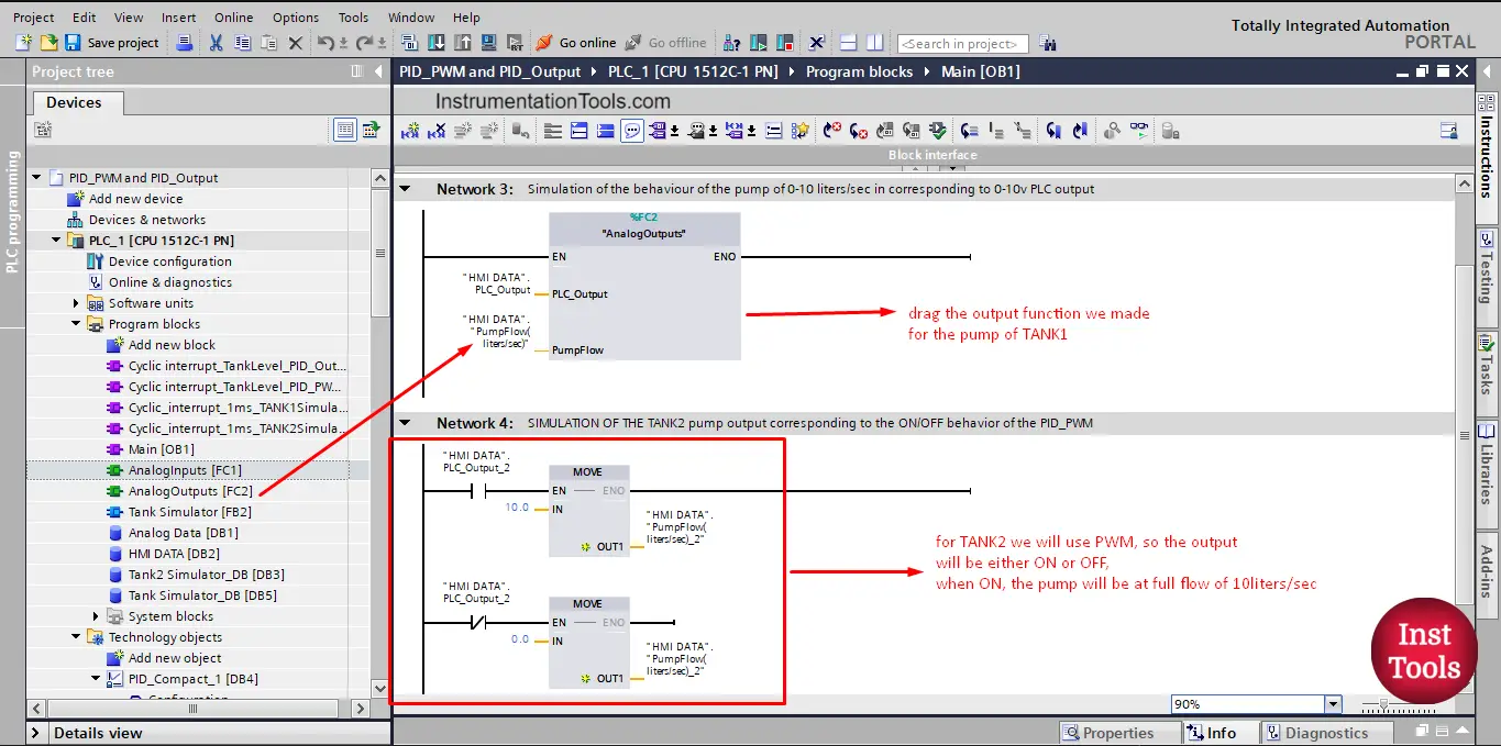
picture 4. Program the tank’s output pumps.
As you can see, when there is a true output for tank 2 the pump will give 10 liters/sec and when it is false the pump will give 0 liter/sec.
TANK 2 Simulator Function Block
We created a function block for simulating our tank 1 system to give the system a real-like behavior with our control; we will reuse this function block with our tank 2. See picture 5.
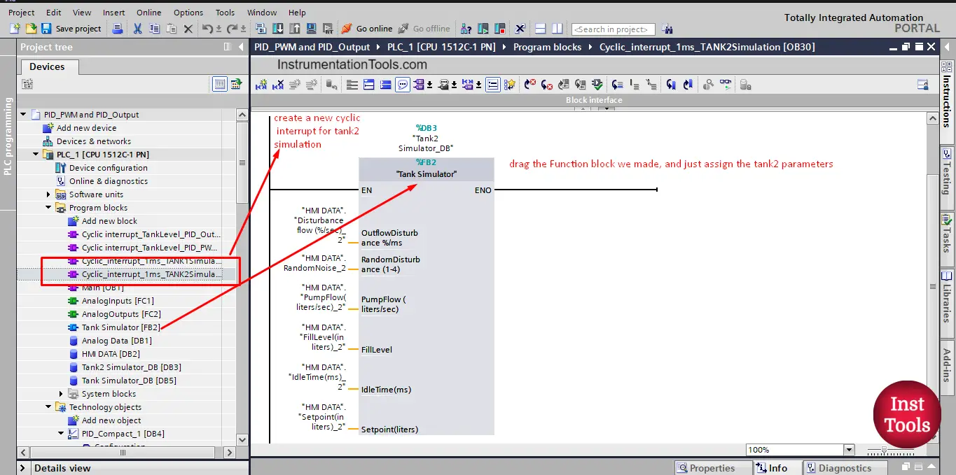
picture 5. Tank 2 simulator block.
As you can see, we created a new cyclic interrupt for our simulator and called our tank simulator function block inside it and we assigned the parameters for tank 2.
One last thing for the sake of simulation is the Empty tank PLC programming to empty the tank when we need to. See picture 6.
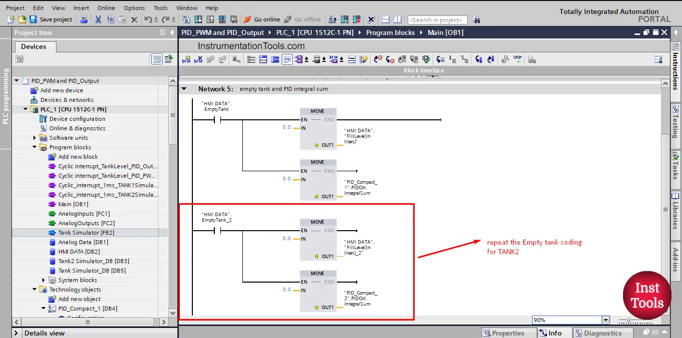
picture 6. Empty tank code.
Adding and Configuring the PID Block for TANK 2
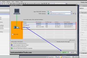
To add a new PID block for our tank 2, we first need to add a cyclic interrupt OB as we explained before. And inside this cyclic interrupt, we will call the Compact PID block. See picture 7.
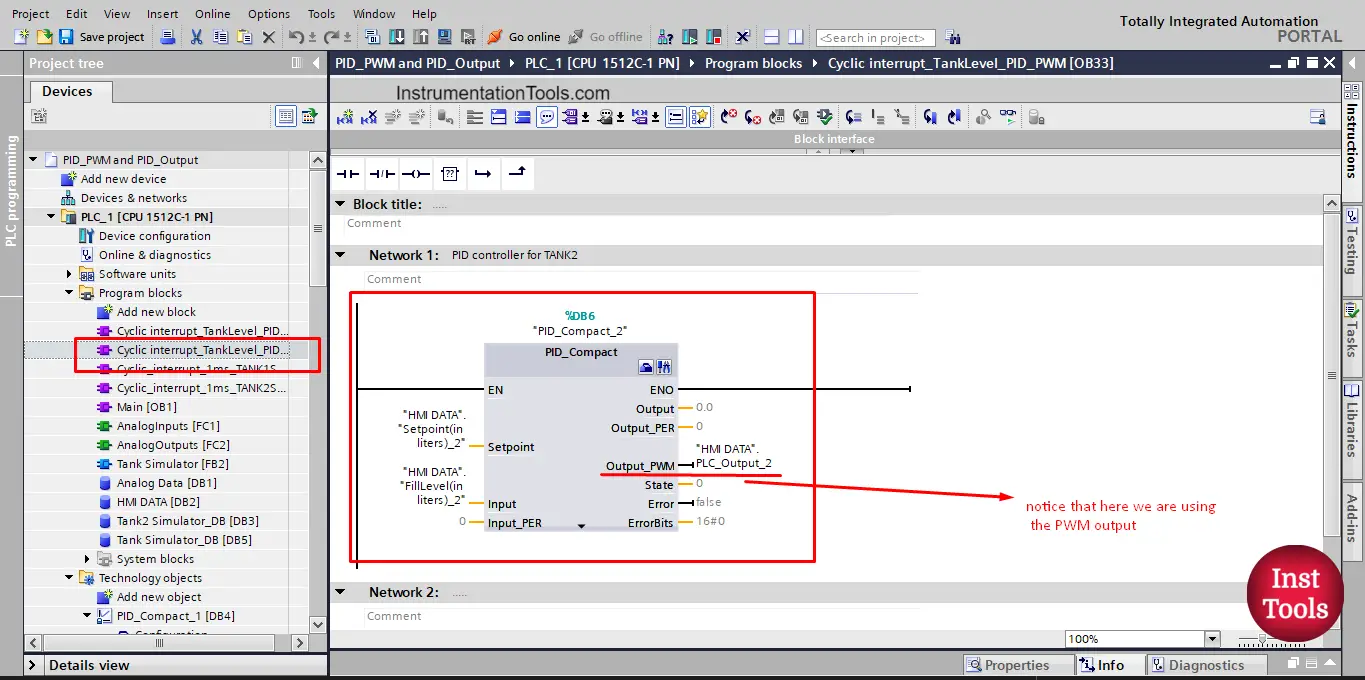
picture 7. Add the PID block.
After that, we will go to the configuration view to configure the PID block with the tank 2 system. See picture 8.
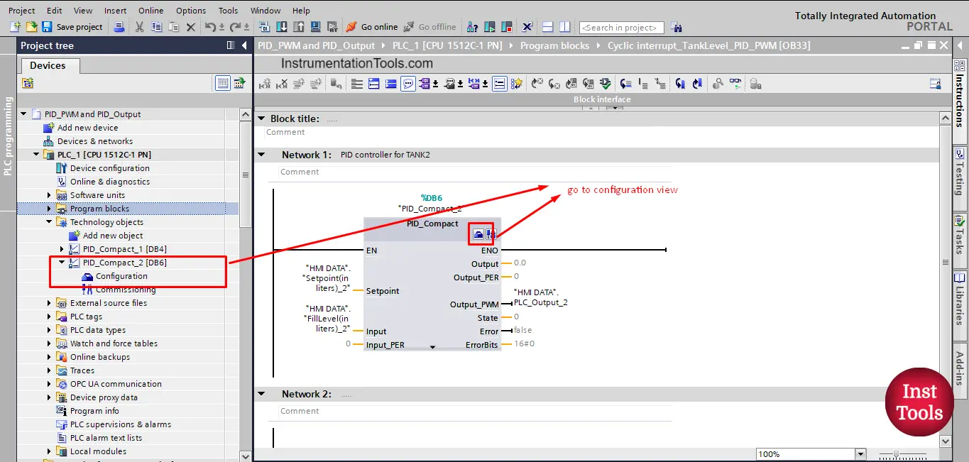
picture 8. Configuration of the PID block.
The configuration of the PID block will mostly be the same as we did for tank 1 except for the parts related to the PWM output. See picture 9 for the basic setting of our PID block.
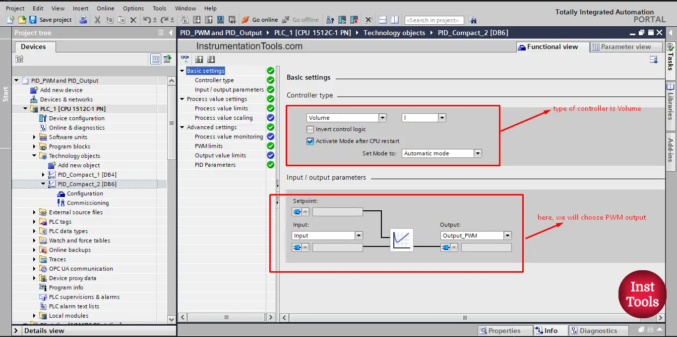
picture 9. Basic setting of the PID block.
As you can see, we have a tank 2 system, so the controller type will be volume as tank 1. Also, notice that the output now is set to Output_PWM.
Next, we configure the process value setting; s tank 2 is the same as tank 1, so our limits will be from 0 liters to 50 liters. See picture 10.
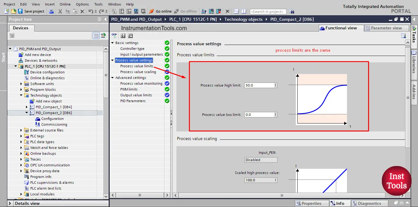
picture 10. Process value limits of tank 2
For the advanced setting, we will need to set the PWM limits as we have the Output_PWM configured. See picture 11
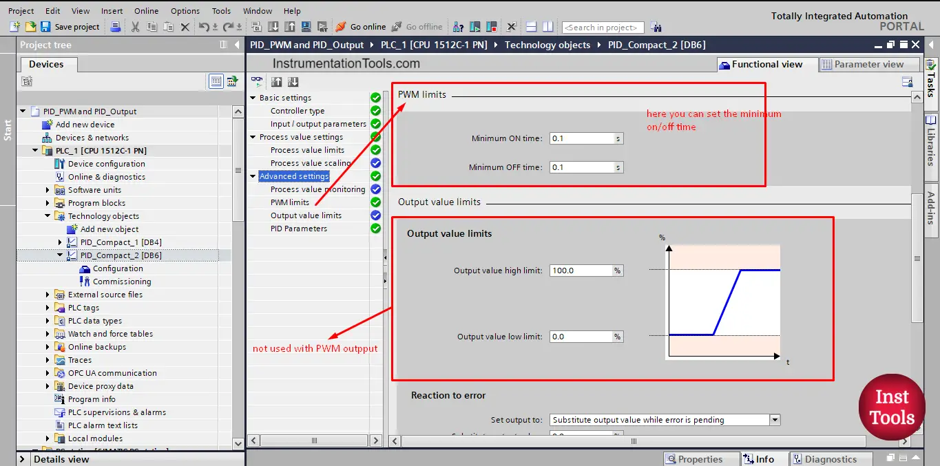
picture 11. PWM limits
For the sake of simulation, we made the minimum and maximum ON time of the pump to 0.1s instead of 0 sec, to be able to see the ON/OFF of the pump easily. In a real system, this limit might be a little longer to protect the pump from burning out.
We also can assign the PID controller parameters if we have the tuning parameters of our system. see picture 12.
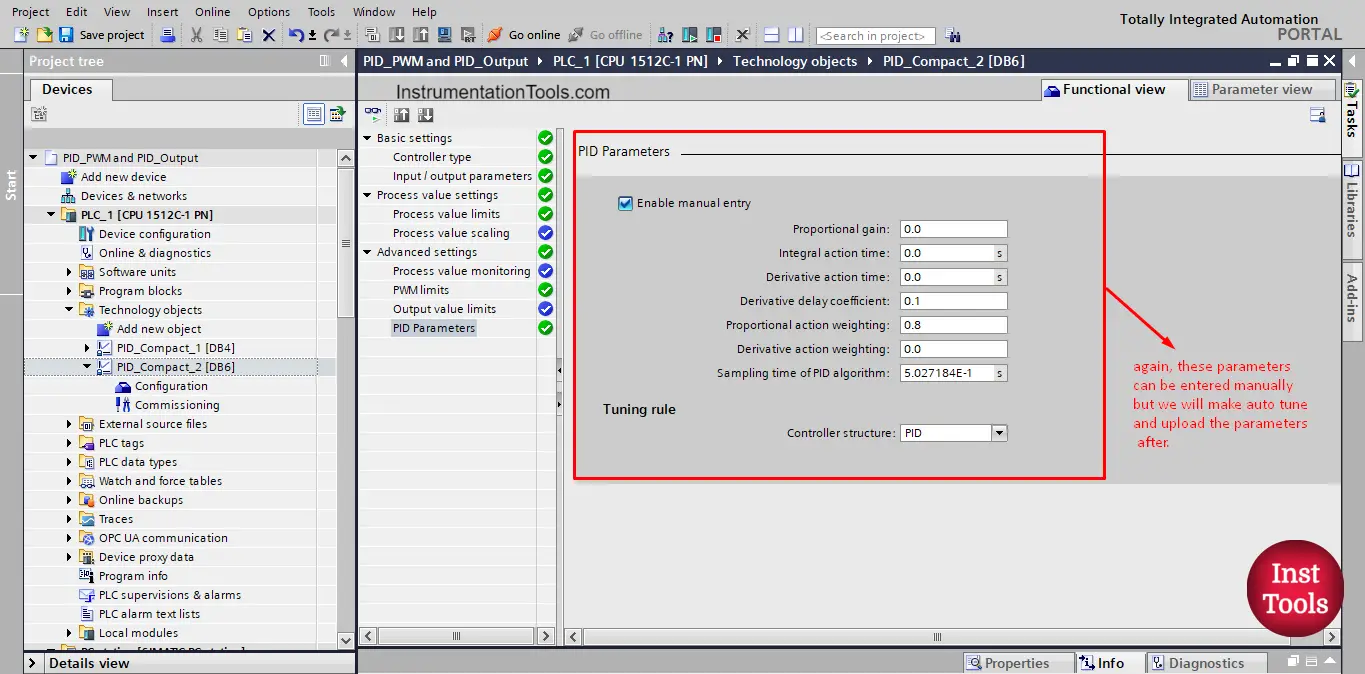
picture 12. PID parameters.
We won’t add any parameters as we will make auto-tuning.
Explain the HMI Visualization
To be able to compare between the system behavior with the PWM output and output_PER we made the HMI visualization as you can see in pictures 13 and 14.
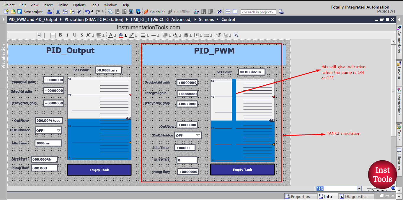
picture 13. HMI simulation.
picture 14. Tank 1 and Tank 2 simulation system
Auto-tuning of the PID Controller
Putting the two tanks together will make it easier for our eyes to notice the different behavior of each tank system with the different PID output. In the last article we showed the auto-tuning procedure of the Output_PER PID block, so this time we will only show the auto-tuning of the Output_PWM of the PID block. See the next simulation video.
You can see from the video, that the tuning was done easily using the TIA Portal, and the tank 2 system is stable and reaches the set point required in a reasonable manner. Notice the PWM of the PID output in the graph representation. Also, notice the ON/OFF behavior of the pump.
See the next simulation video comparing the behavior of the two tank systems.
You may say that the tank 1 system is more stable and reaches the set point faster, but tank 2 is also a very accepted system. And both systems are ok. Off course in our case, the Output_PER is better because it has the advantage of using the full range of pump output from 0 to 10 liters/sec.
Try to run the simulation provided in the article and experiment with different conditions and parameters and see how the two tank systems will react.
Download: PID Program
Conclusion
- Function and Function blocks are very useful when designed to be reusable.
- A PID controller has many types of output you can use, and all of them will get the job done.
- The Output_PWM will be more effective in the systems that already have on/off outputs like SSRs with heaters.
If you liked this article, then please subscribe to our YouTube Channel for Instrumentation, Electrical, PLC, and SCADA video tutorials.
You can also follow us on Facebook and Twitter to receive daily updates.
Read Next:
- PID Controllers in Closed Loop
- Update PLC Firmware Version
- PLC ON-OFF Control with Hysteresis
- Design Counters in PLC Program
- Timer and Counter in PLC Logic