In the last article, we talked about creating faceplates in your HMI project for multiple similar systems in your project. We showed how to edit and modify the faceplate in the library view and also how to create properties for your faceplate interface. In this article, we will show how to connect these properties to the PLC project.
Contents:
- Connect faceplate properties to the PLC project.
- Program simulation.
- Conclusions.
Connecting Faceplates to PLC Project
In the last article, we created a faceplate for our tank system, and we created some properties for that faceplate.
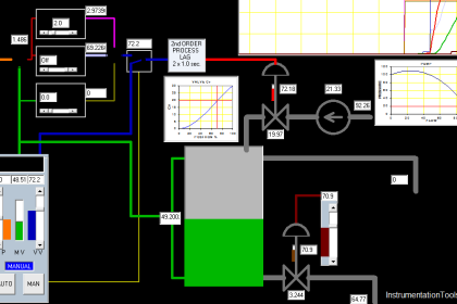
We designed the faceplate to have 4 simple visualizations of our tank, the tank fill level, the set point, and the %outflow, and for the sake of simulation, we added a button to empty the tank when needed. And we gave our faceplate 4 properties to represent these elements. See picture 1.
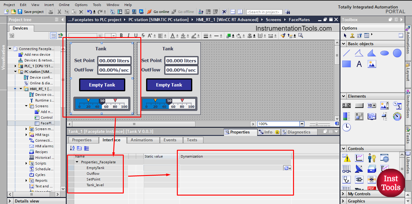
picture 1. Properties of the faceplate.
To connect the properties of the faceplate to our PLC project, we first need to determine what these properties do inside the faceplate, up till now, these properties don’t really do anything, they are just elements of your faceplate, we need to configure these properties with the elements of the faceplate.
We need to edit the faceplate to do that, Right-click on the faceplate and choose edit faceplate. See picture 2.
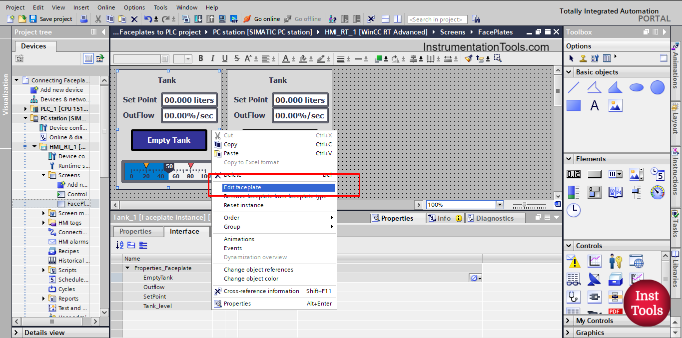
picture 2. Edit faceplate.
This will open the library view and create a new faceplate version in the work. See picture 3.
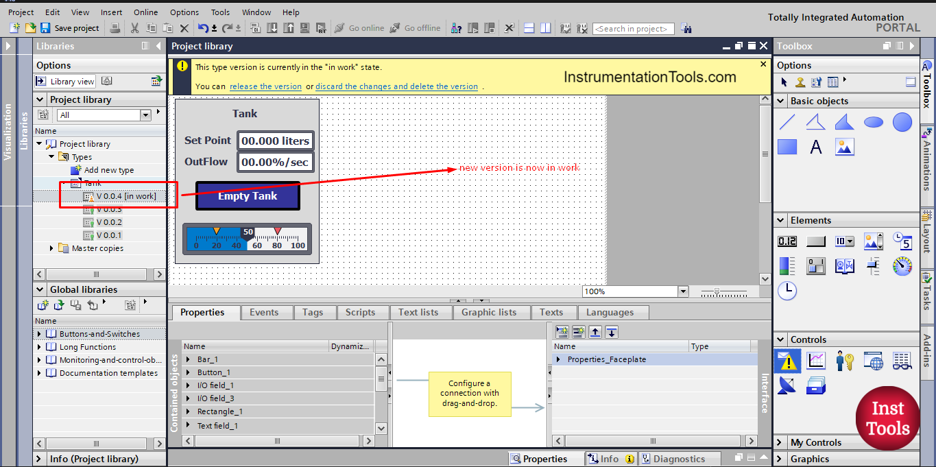
picture 3. The new faceplate version in work is opened.
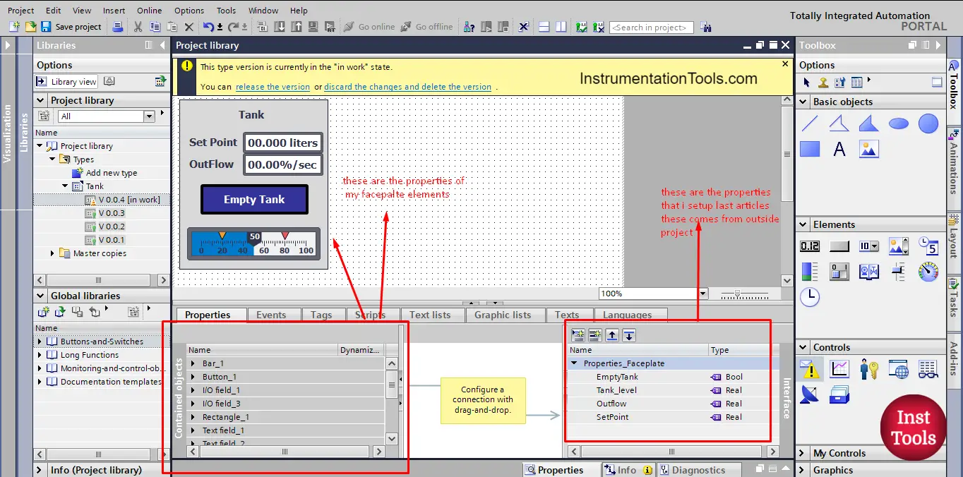
Once you’re in the library view you will see the properties that we created last article, and you will also see the elements of the faceplate, we need to connect them together. See picture 4.
picture 4. Properties of the faceplate.
As you can see, your faceplate elements are all written on the properties side on the left. Any element to select in the faceplate will highlight its properties in the left side section.
For example, if you select the I/O field of the %outflow it will highlight the properties of the element. See picture 5.
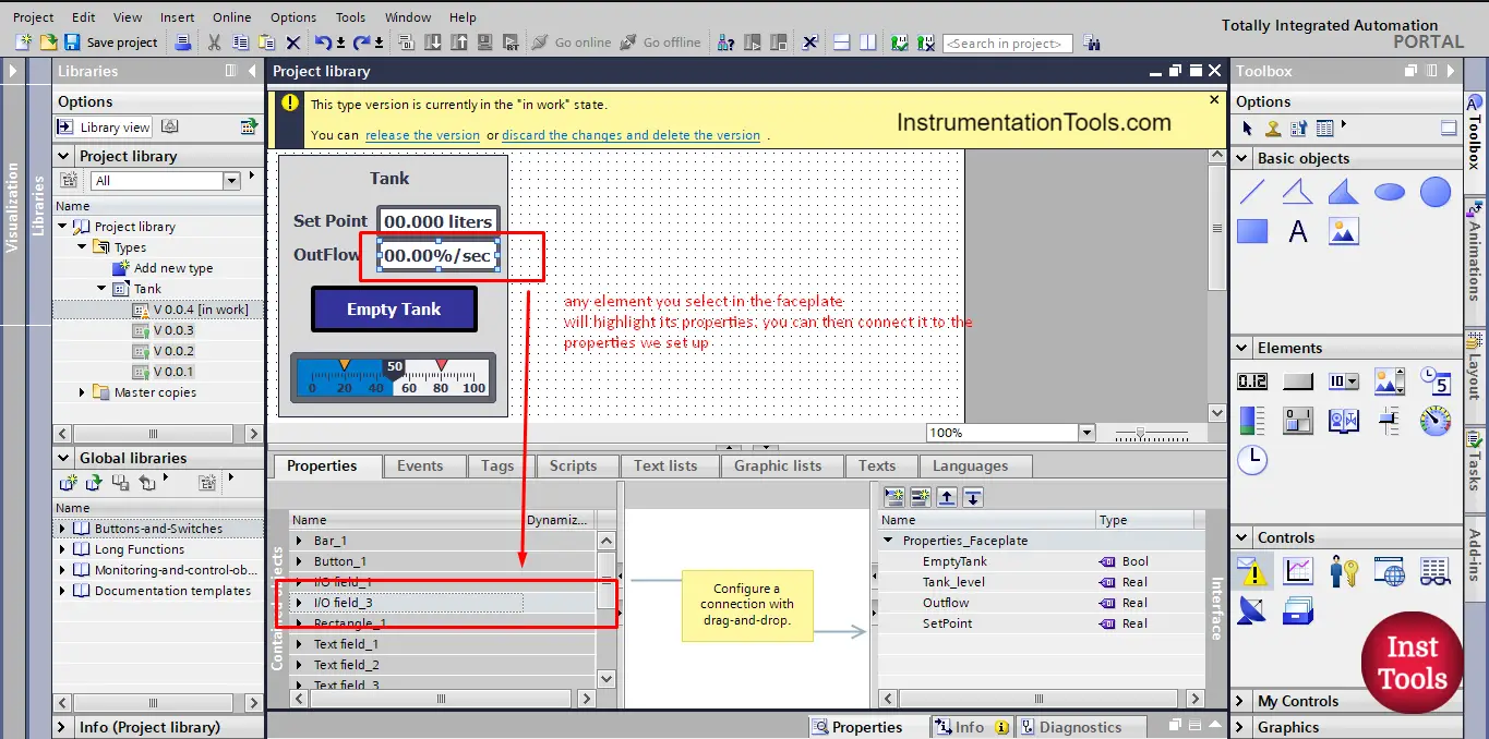
picture 5. Properties of I/O field_3
Another example is if you select the empty tank button, it will highlight its properties in the properties area. See picture 6.
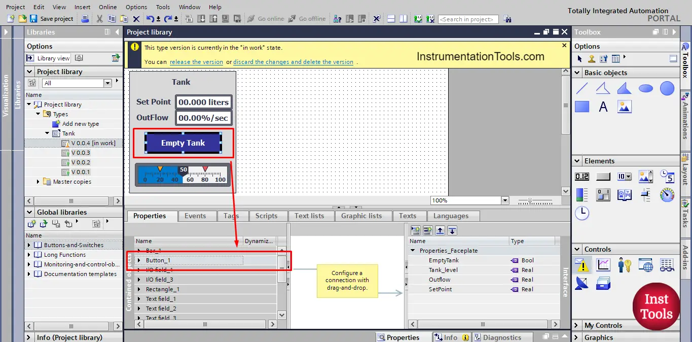
picture 6. Properties of Button_1
Now, how to connect the elements of my faceplate to the properties we created, to do so we simply select the property of the faceplate element we need to connect to the outside plc project and just drag and drop to connect it to the interface properties.
For example, we want to connect the process value of the set point I/O field to the set point properties we created in the interface. See picture 7.
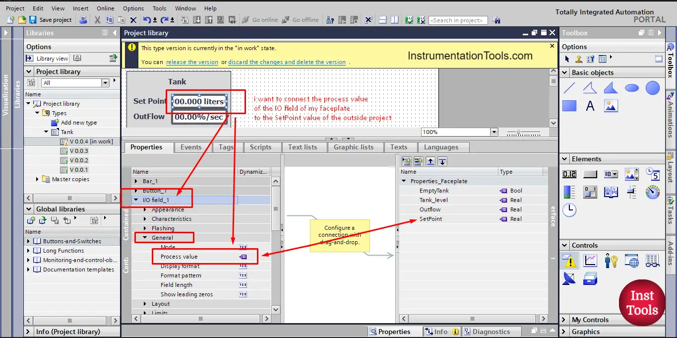
picture 7. Process value of I/O field_1
First, we find the property we want, in this case, it is the process value as you can see, then we just drag it and drop it in the interface area on the right, make sure to connect it to the set point tag we created in the interface. See picture 8.
picture 8. Connect set point process value.
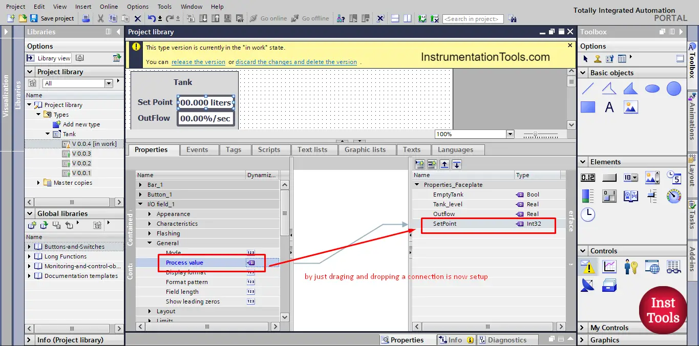
Note that, make sure the date type of your tags are correct, sometimes TIA Portal will change the data type after you drag and drop your process value.
As you can see the data type changed to Int32 but we need it to be Real to match the actual PLC project data type. We need to change it back to Real data type. See picture 9.
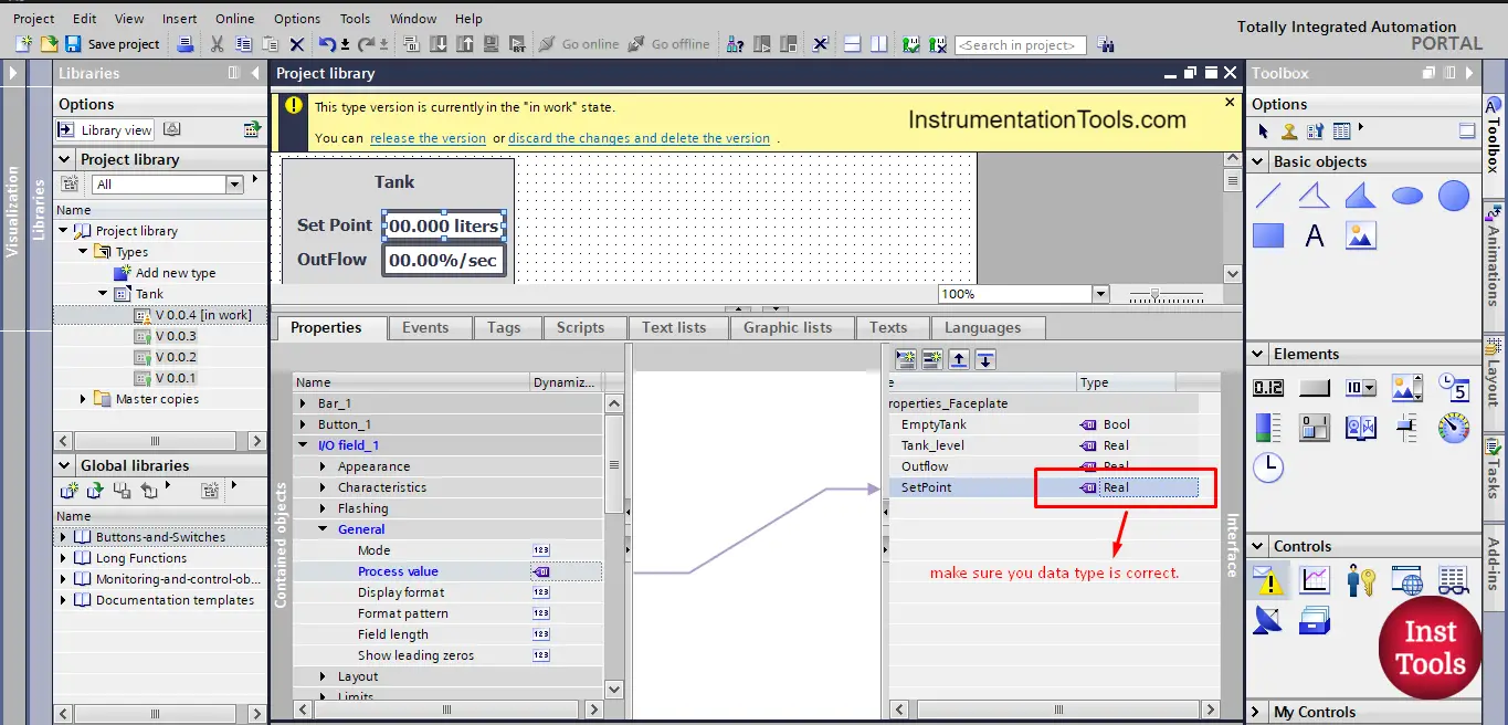
picture 9. Make sure data type is correct.
Next, we need to connect the process value of the outflow I/O field to the Outflow property in the interface area, we will just repeat what we did with the set point. See picture 10.
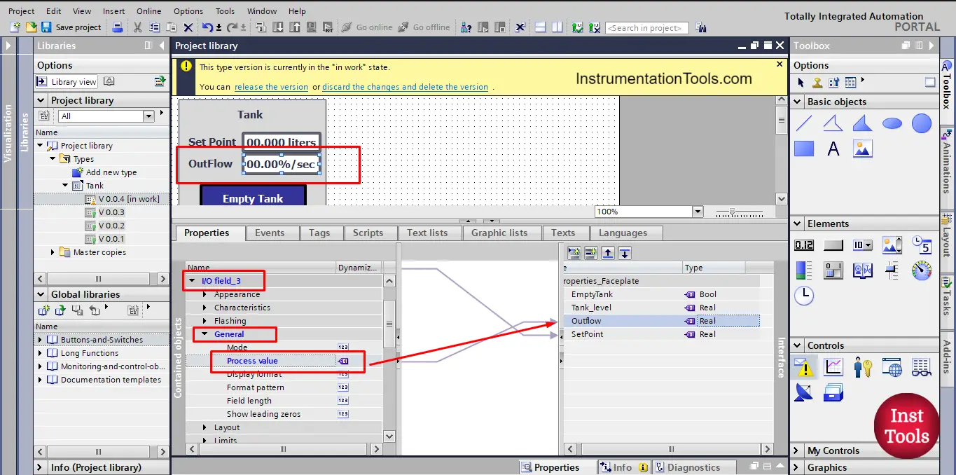
picture 10. Connect outflow process value.
Each connection you make will be indicated by an arrow that is automatically drawn between the interface area and the properties area. See picture 11.
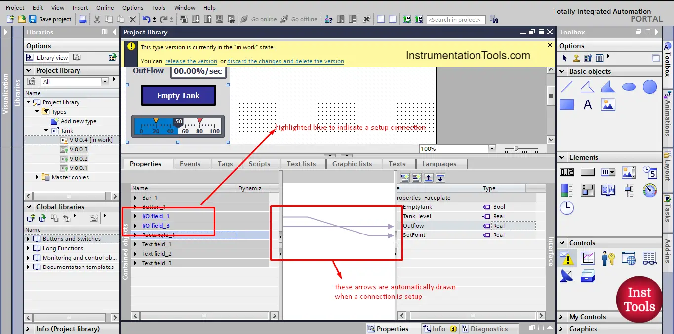
picture 11. Connection arrows are automatically drawn.
Let’s release the new version and see the effect of our connections. See picture 12.
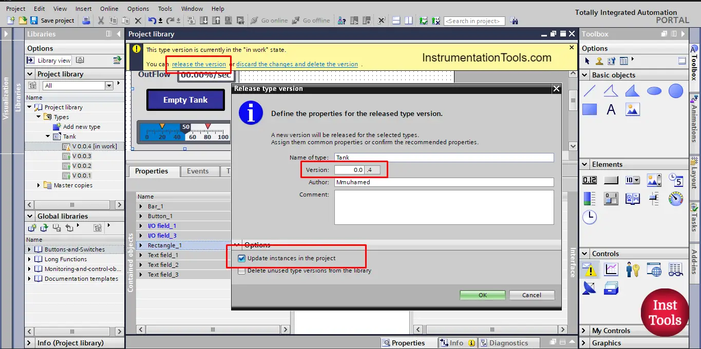
picture 12. Release the new version.
Don’t forget to update instances in the project to apply the new changes to all instances in the project.
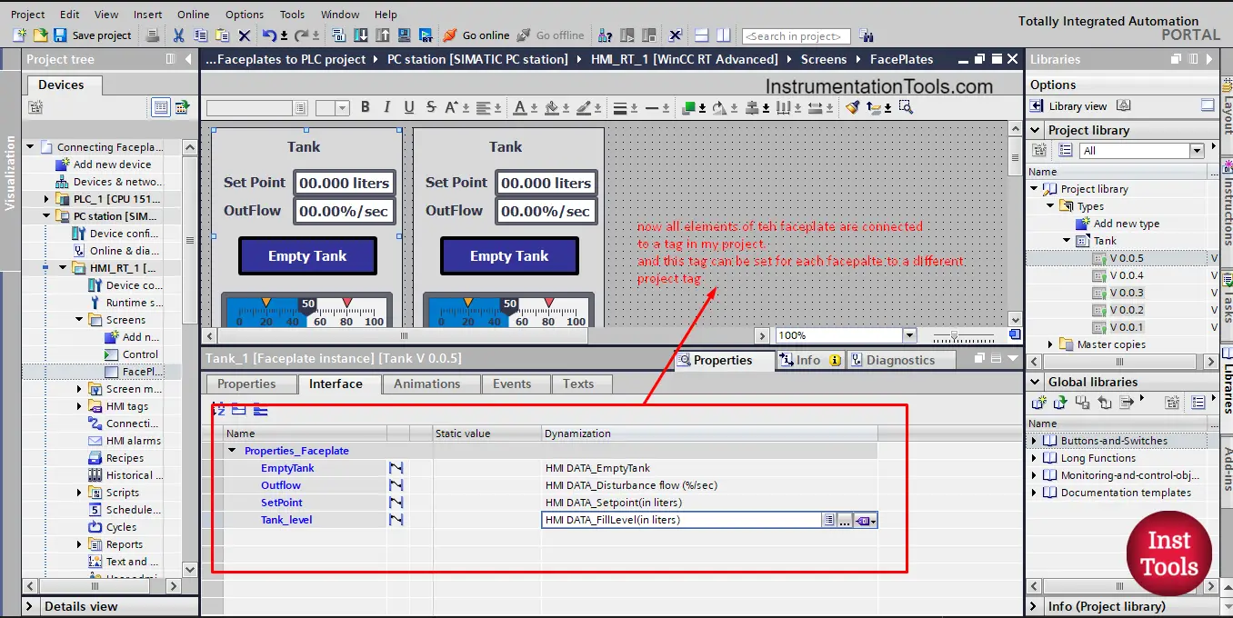
Now, we can connect the faceplate properties to our PLC project, see picture 13.
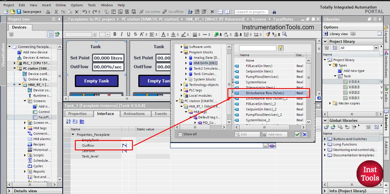
picture 13. Connect outflow property to PLC tag.
The small blue line next to the Outflow and Setpoint in the properties area indicates that these properties are connected to some elements inside the faceplate.
Now, we can connect each faceplate instance to a different tank by just choosing the tags of this tank. For the faceplate of tank 1, See picture 14.
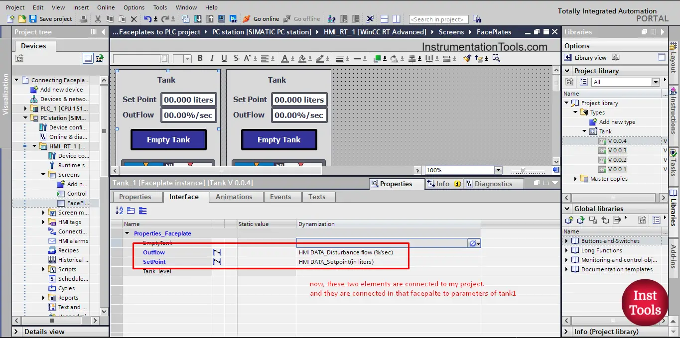
Picture 14. Tank 1 faceplate parameters.
For a different tank, we will just select the tags of this tank, see the connection tags of tank 2 in picture 15.
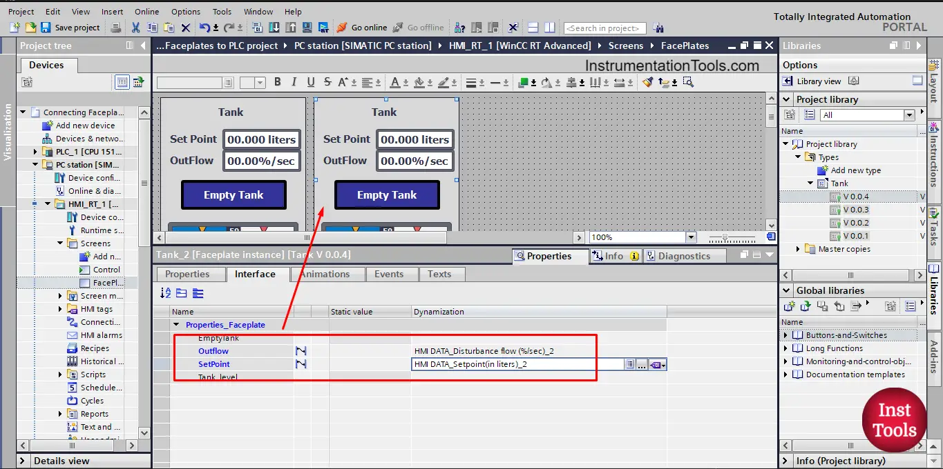
picture 15. Tank 2 connection tags.
We now, made the connection to two elements of our faceplate, but we still need to make the connection for the rest of the elements, the Empty Tank Button and the Tank fill level Bar. To do so, we will edit the faceplate again to make these connections.
For the Empty Tank Button, the process value will be dragged and dropped to the EmptyTank Bool in the interface properties. See picture 16.
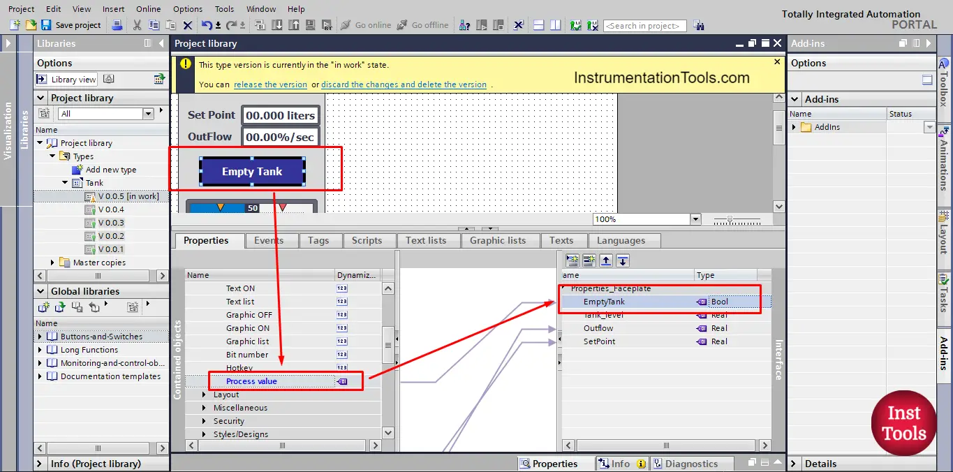
picture 16. Process value of the Empty tank button.
Note that, the value is now connected to the outside project, but the button is still not configured to do anything, don’t forget, this is still an HMI visualization so we have to configure the elements we create.
In this case, I want to use the button to set the value of the EmptyTank tag inside the PLC to 1 while the button is pressed and back to 0 when the button is released. We can do that simply from the properties of the Button itself as you would do with any HMI button. See picture 17.
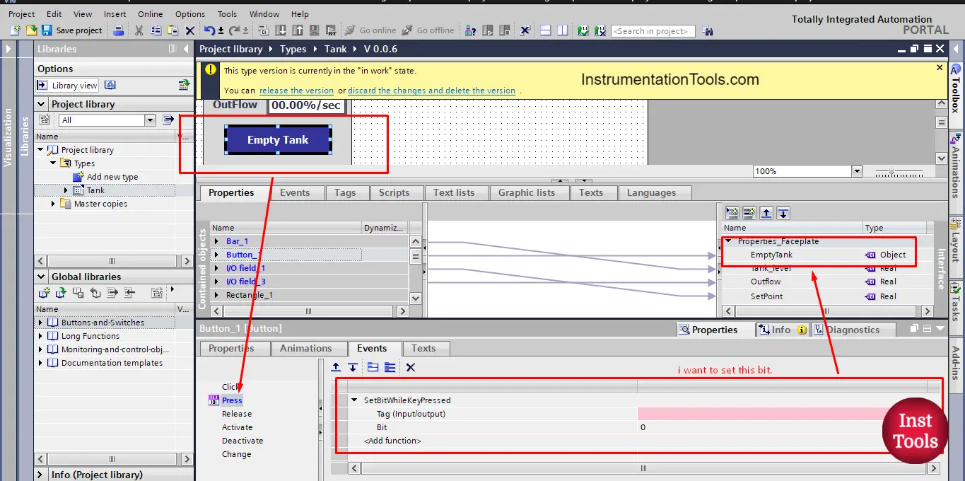
picture 17. Button _1 properties
while the key is pressed I want to set the EmptyTank tag. To do this I need to select it from properties. See picture 18.
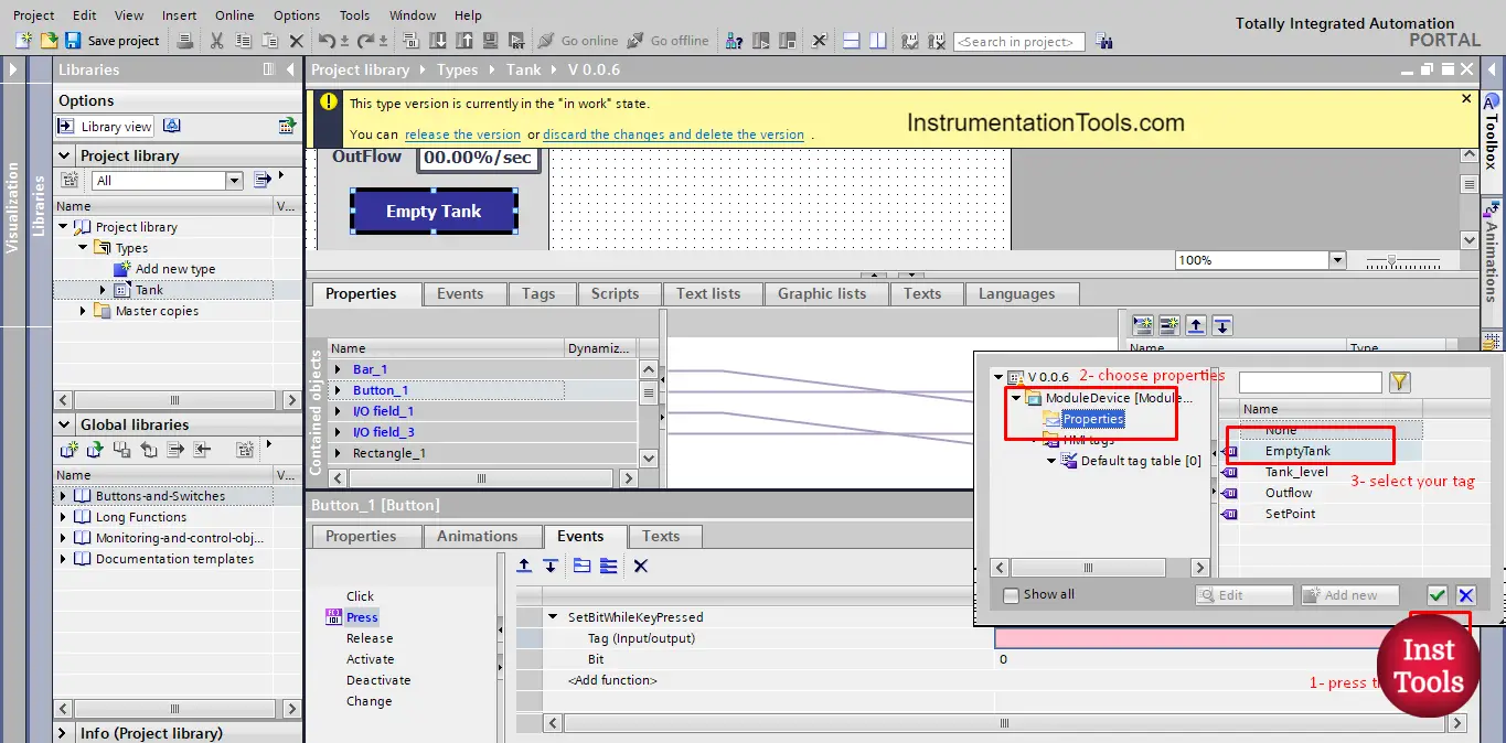
picture 18. Choose the property tag you need.
Now pressing the Empty Tank Button will set the EmptyTank tag in the properties. See picture 19.
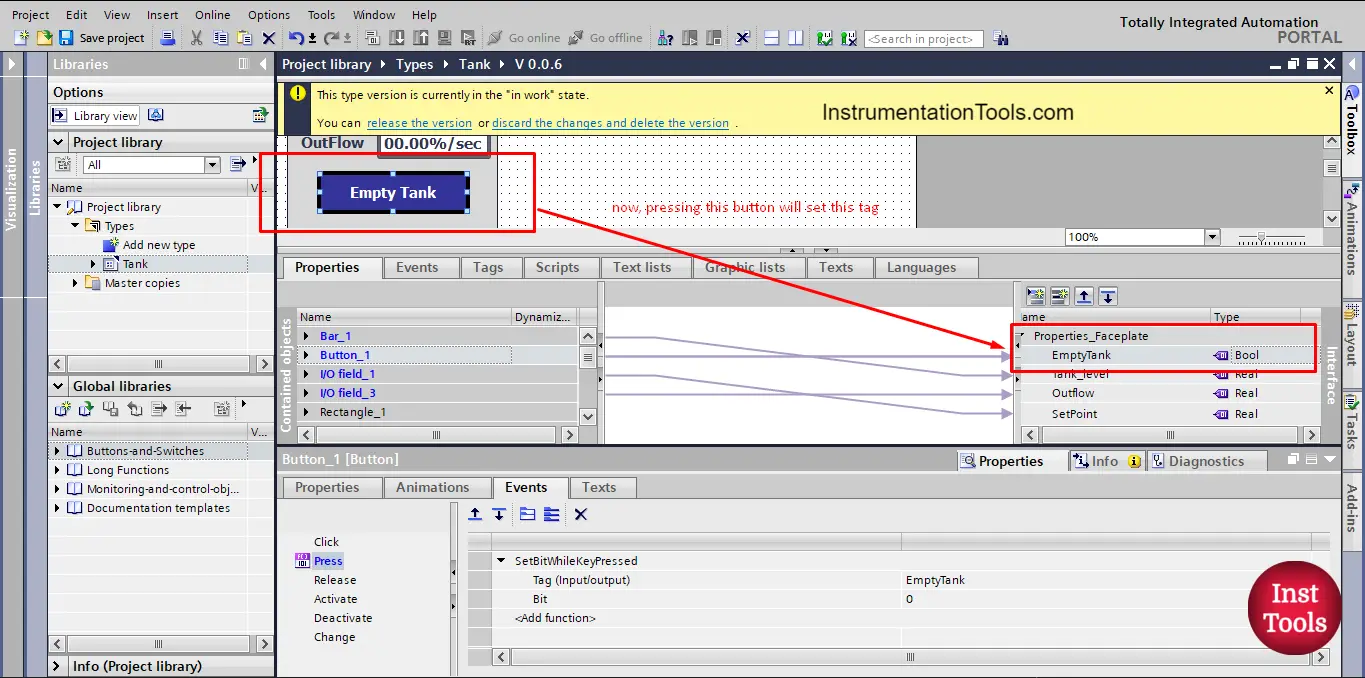
picture 19. Pressing the Button will set the EmptyTank tag.
The last element we need to connect is the tank fill level bar, just drag and drop the process value as we did before. See picture 20.
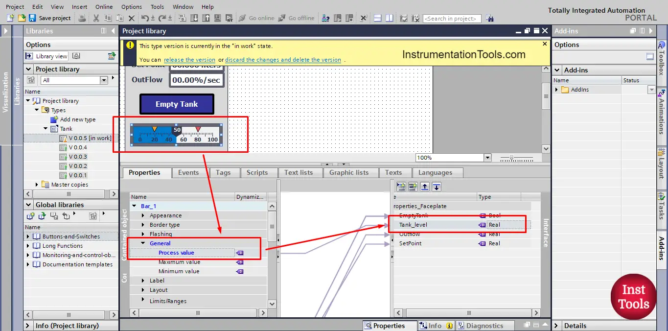
picture 20. Tank fill level process value.
Now each element in the faceplate is connected to a property that can be linked to the PLC project. See picture 21.
picture 21. Tank 1 tags connected to faceplate instance.
Now, each faceplate instance can be connected to different PLC project tags, if I have 2 tanks I will use 2 faceplates and assign the proper tags for each faceplate. And the same if I have more than 2 tanks.
HMI Program simulation
We will assume 2 tanks in our system and we will use two faceplate instances in our HMI, and we will select the tags of each faceplate to represent a tank of our system.
See the following simulation video.
From the video, you can see that the two faceplate instances are completely independent of each other, each faceplate represents only one tank and behaves to the changes of that tank system alone.
So, we were able to create a global visualization that can be used for any tank system I have in my project.
Download: Faceplates and PLC
Conclusion
- You connect a faceplate element to interface properties by a simple drag-and-drop action.
- You can use faceplate instances with multiple numbers of the same system, by just applying the corresponding tags to the faceplate interface.
If you liked this article, then please subscribe to our YouTube Channel for Instrumentation, Electrical, PLC, and SCADA video tutorials.
You can also follow us on Facebook and Twitter to receive daily updates.
Read Next:
- PLC PID Controller Output Types
- Static and Temp Variables in PLC
- Power Supply Sizing for Systems
- How to Read the PLC Datasheet?
- Update the Firmware Version of PLC