AS-Interface is an intelligent cabling system with a master-slave bus. 32 slaves addressed from 1 to 31 or with extended addressing 64 slaves addressing 1 to 31A, 1 to 31B can be connected.
Each slave can transfer up to four inputs and four outputs in one bus cycle. In addition, it provides a unique wiring system that is fast, easy to wire, and easy to operate.
AS-interface Communication
The network can have a cumulative cable length of 100 meters. Repeaters are used for large-scale systems. The power supply must be located for every 100 meters, a maximum of 2 repeaters per single cable. Therefore, the total run is 300 meters.
It works at the lowest level of the Fieldbus hierarchy, but when implemented with an AS-i master/gateway (sometimes simply called an AS-i gateway) it can connect to a higher-level network, such as PROFIBUS, DeviceNet, Ethernet/ IP, or others.
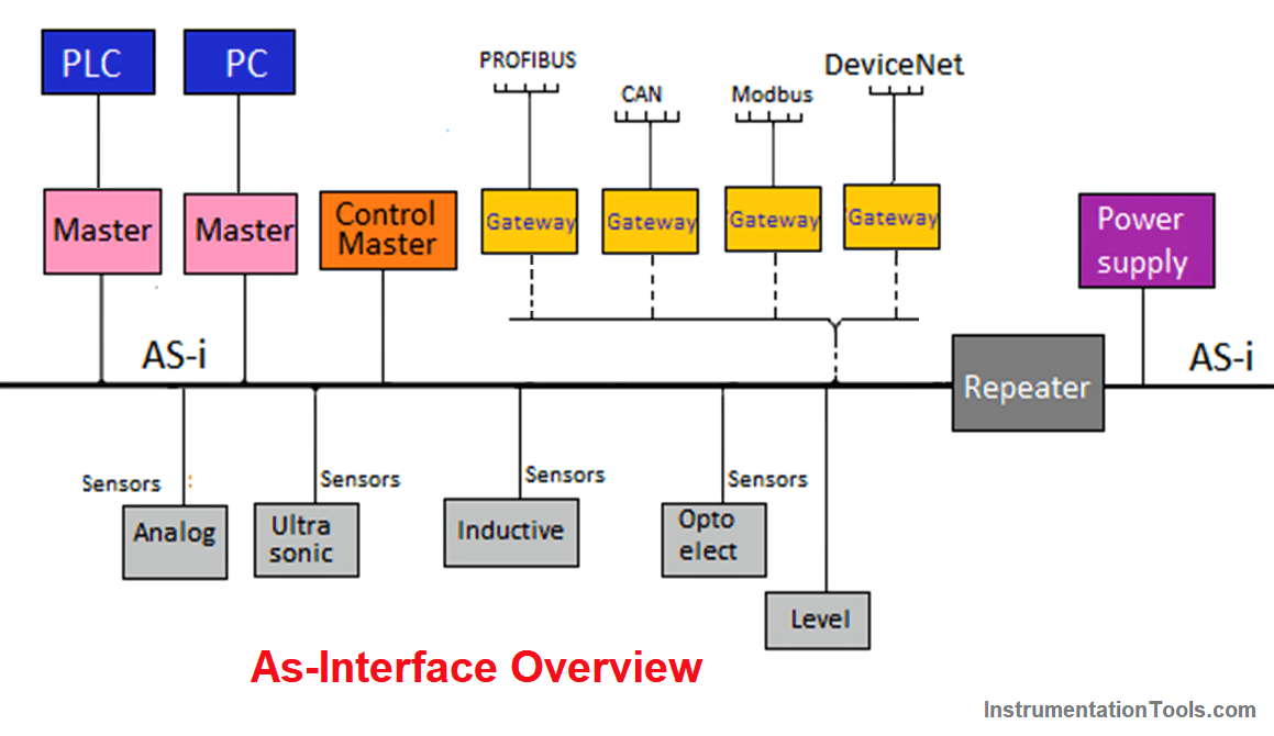
As a general rule, AS-i masters are connected to higher-level control, such as a PLC (Programmable Logic Controller), a PC-based control, or a DCS (Distributed Control System).
Traditionally, sensors and actuators have been connected to PLCs or other controllers through discrete wiring and cable harnesses. But, the introduction of the actuator-sensor interface, also known as AS-Interface, or AS-i (an acronym for Actuator Sensor Interface), in the 1990s offered users and integrators a reliable and cost-effective replacement for the cumbersome and slow of parallel wiring.
Why is AS-i used?
As can be seen in the present environment, replacing simple sensors and actuators with AS-interface sensors and actuators is an upgraded trend in automation.
AS-Interface is already an existing standard worldwide for networking simple I/O. It is a two-wire network for analog, discrete I/O, intelligent sensors.
Its potential to cost-effectively replace the messy nest of cables that permeates most industrial facilities is highly attractive in many industries.
Of the low-level sensor/actuator replacement networks available, AS-Interface offers the highest performance at the lowest cost. Due to its roots as a Siemens network, AS-Interface is already enthusiastically supported by the industrial automation community in Europe.
Today, many automation vendors are attracted by its high speed, bus power, ease of operation, and insulation displacement cabling.
As control engineers become more and more comfortable with a structured network system, AS-Interface is the perfect solution for the lowest level of network architecture, those simple, low-level sensors and actuators that consume the most power. The cost of installation is cheap, easy commissioning, and troubleshooting.
DeviceNet
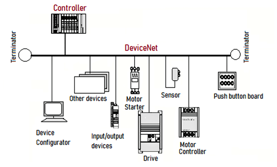
The DeviceNet is a multi-point, digital network for connection between sensors, actuators, and industrial automation systems. This technology was developed to facilitate maximum flexibility between field equipment and interoperability between different manufacturers.
The DeviceNet network is classified at the network level called the device bus, whose main characteristics are: high-speed, byte-level communication that includes communication with discrete and analog equipment, and high diagnostic power of network devices.
DeviceNet Technology
It is an open automation standard to transport two main types of information:
- Cyclic data from sensors and actuators, directly related to control.
- Non-cyclical data is indirectly related to the control, such as configuration and diagnostics.
Cyclic data: It represents the information exchanged periodically between the field equipment and the controller.
Non-cyclic data: On the other hand, the non-cyclical ones are information eventually exchanged during the configuration or diagnosis of the field equipment.
The physical and access layer to the DeviceNet network is based on CAN (Controller Area Network) technology and the upper layers on the CIP (Common Application Layer) protocol.
A DeviceNet network can have up to 64 devices, each one occupying a node on the network, addressed from 0 to 63. Any of them can be used, although the use of address 63 is not recommended, since it is used for commissioning.
Network Characteristics
Topology is based on the main bus with branches. The main bus must be made with the thick DeviceNet cable and the branches with the thin or flat DeviceNet cable.
Similar cables may be used as long as their electrical and mechanical characteristics are compatible with the specifications of standard DeviceNet cables.
Other features to highlight are
DeviceNet permits the use of routers, bridges, repeaters, and gateways.
The network supports up to 64 DeviceNet stations (nodes), including the master, addressed from 0 to 63 (MAC ID).
2-pair cable: one for 24V power supply and one for communication.
- Ability to insert and change hot, without interrupting the network.
- Compatible with equipment powered by the 24V network or as having its source.
- Use of open or closed connectors.
- Protection against reverse connection and short-circuit.
- High current capacity in the network (up to 16 A).
- Uses the same power from the power supply.
- Several sources can be used in the same network to meet the needs of the application in terms of load and cable length.
- Selectable communication speed: 125,250 and 500 kbps.
- DeviceNet communication is based on I/O connections and the question and answer model.
- Diagnosis of each field equipment and the network.
- Capable of transport of discrete and analog control data.
- Very well communication mechanism for electromagnetic interference.
DeviceNet is one of the three open and standardized network technologies whose application layer uses CIP, along with ControlNet and Ethernet/IP, it has a common object structure. That is, it is independent of the physical medium and the data link layer.
It uses a standard application layer integrated with open hardware and software interfaces, it constitutes a universal connection platform between components in an automation system, from the factory to the internet level.
Communication modes
The DeviceNet protocol has two basic types of messages, cyclic I/O, and explicit message.
Each of them is suitable for a certain type of data, as described below:
Cyclic I/O: This type of (synchronous) message data is given over to priority data processing between a producer and one or more consumers. They are divided as per the data exchange method. The main ones are:
# Change of State: Exchange of data between master and slave takes place when there are changes in the monitored or controlled values, up to a certain time limit. When the time limit is reached, transmission and receiving take place without alterations. The time variable configuration can be done in the network configuration program.
# Cyclic: another method of communication very similar to the previous one. The only difference is in the production and consumption of messages. In this type, all data exchange occurs at regular time intervals, regardless of being altered or not. This period is also set in the network configuration software.
# Bit-strobe: Communication method where the master sends a message data over the network with 8 bytes of data. Each bit of these 8 bytes represents a slave that is addressed and responds as programmed.
# Polled: It is a communication method in which the master sends a message to each of its lists of slaves (scan list). Likewise, as soon as it receives the request from the master, the slave quickly responds to said request. This process is repeated until all are consulted, restarting the cycle.
Explicit message: type of message for general use and not a priority. Mainly used in asynchronous tasks such as parameterization and configuration of the equipment.
Physical layer and transmission medium
DeviceNet uses a main/drop bus network topology that allows both communication and power to be present on the same cable.
This power supply is supplied by a source directly connected to the network, and has the following characteristics:
- 24Vdc.
- DC output isolated from AC input.
- The current capacity is compatible with the installed equipment.
- The total size of the network varies according to the transmission speed (125, 250, 500 Kbps).
Network topology
DeviceNet specifications define the topology and allowable components. The variety of possible topologies is shown in the below figure.
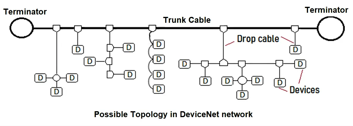
The specification also addresses the grounding system, a mix between thick and thin cable, terminators, and input power.
The basic trunk line-dropline topology uses one cable (2 separate twisted pairs for power and signal). Thick (thick) or thin (thin) cable can be used for main lines or branches.
The below table is of Cable lengths for different data transmission speeds.
| Data Speed | 125 Kbps | 250 Kbps | 500 Kbps |
| Length of the main bus with thick cable (thick trunk) | 500 m | 250 m | 100 m |
| Length of the main bus with thin cable (thin trunk) | 100 m | 100 m | 100 m |
| Maximum length for a branch of the main bus (maximum drop) | 6 m | 6 m | 6 m |
| Length of the branches added to the main bus (cumulative drop) | 156 m | 78 m | 39 m |
Cables for DeviceNet
There are 4 types of standardized cables: thick, medium, thin, which have similar characteristics in terms of shape and type of insulation, and flat cable.
The most common or used is the thick cable for the bus and the thin cable for the taps.