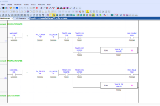
Suppose we have a PLC connected to three pushbutton switches as shown in this illustration:
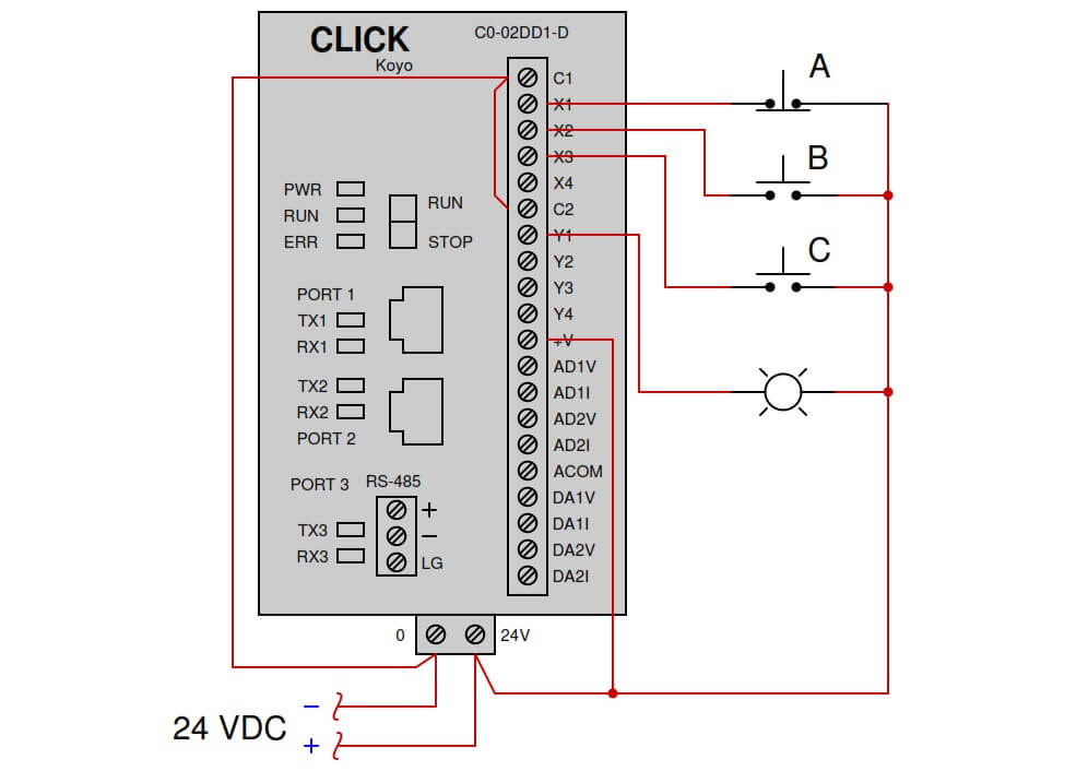
Sketch a Ladder Diagram program for this PLC to energize the lamp if the following input conditions are met:
- Either switch A or switch B pressed
- Switch C unpressed
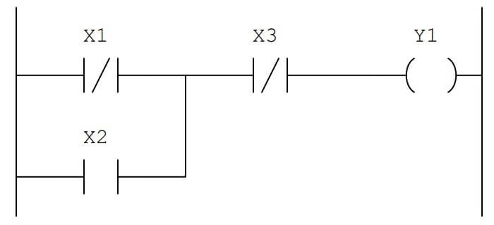
Answer:
Share Your Answer / Comments
Pushbutton Example
Credits : by Tony R. Kuphaldt
Read Next:
- Problem in the PLC Program
- Troubleshooting PLC Inputs
- Storage Area PLC Logic
- PLC Sequential Operation
- Do’s and Don’ts in PLC


The ladder u have shown .in answer is wrong …