Inst ToolsInst ToolsInst Tools
  • Courses
  • Automation
    • PLC
    • Control System
    • Safety System
    • Communication
    • Fire & Gas System
  • Instrumentation
    • Design
    • Pressure
    • Temperature
    • Flow
    • Level
    • Vibration
    • Analyzer
    • Control Valve
    • Switch
    • Calibration
    • Erection & Commissioning
  • Interview
    • Instrumentation
    • Electrical
    • Electronics
    • Practical
  • Q&A
    • Instrumentation
    • Control System
    • Electrical
    • Electronics
    • Analog Electronics
    • Digital Electronics
    • Power Electronics
    • Microprocessor
  • Request
Search
  • Books
  • Software
  • Projects
  • Process
  • Tools
  • Basics
  • Formula
  • Power Plant
  • Root Cause Analysis
  • Electrical Basics
  • Animation
  • Standards
  • 4-20 mA Course
  • Siemens PLC Course
Reading: Create an Application in HMI using Tia Portal
Share
Font ResizerAa
Inst ToolsInst Tools
Font ResizerAa
  • Courses
  • Design
  • PLC
  • Interview
  • Control System
Search
  • Courses
  • Automation
    • PLC
    • Control System
    • Safety System
    • Communication
    • Fire & Gas System
  • Instrumentation
    • Design
    • Pressure
    • Temperature
    • Flow
    • Level
    • Vibration
    • Analyzer
    • Control Valve
    • Switch
    • Calibration
    • Erection & Commissioning
  • Interview
    • Instrumentation
    • Electrical
    • Electronics
    • Practical
  • Q&A
    • Instrumentation
    • Control System
    • Electrical
    • Electronics
    • Analog Electronics
    • Digital Electronics
    • Power Electronics
    • Microprocessor
  • Request
Follow US
All rights reserved. Reproduction in whole or in part without written permission is prohibited.
Inst Tools > Blog > PLC Tutorials > Create an Application in HMI using Tia Portal

Create an Application in HMI using Tia Portal

Last updated: March 4, 2021 12:31 pm
Editorial Staff
PLC Tutorials
No Comments
Share
4 Min Read
SHARE

This article is about creating an application (screen) in HMI using Siemens TIA PORTAL.

We all know how much HMI is useful, it allows us to gather all the data from one location.

We can control processes, can see alarms, trends, see the level of the tanks, and can give a command to control valve to see its operation like what we do with HART to check loop.

So, HMI is all in one place where you can do any stuff just you need have to communicate it with the PLC.

In the above window, you can see an example of HMI how it carries all the information. In red symbol, you can see an error and a lot of another feature you can access within HMI.

Also Read: Programmable Logic Controller

Create an Application in HMI

Let’s learn how to create an application, to do that follow the below step as I do.
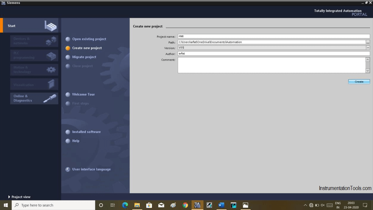
Step 1:

Open TIA PORTAL. Click on “create new project”. Give a name and hit “create”.
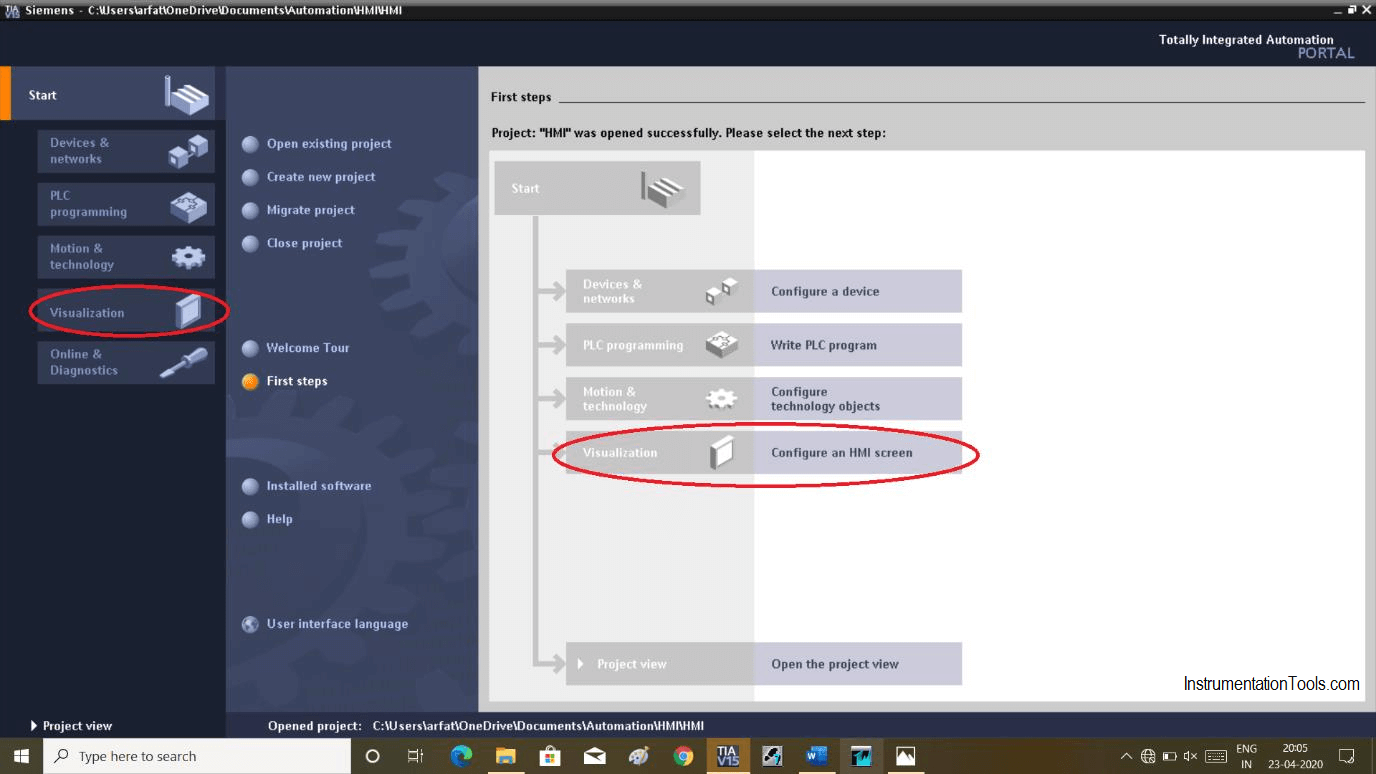
Create a New Project in Siemens

Step 2:

Now click on “visualization” and select any one of them.
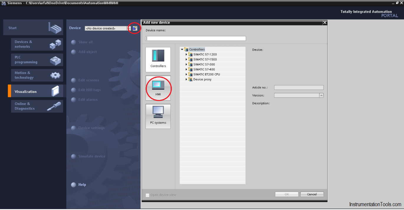
Configure an HMI Screen

Step 3:

Here click on “Add new device” and then select “HMI”.
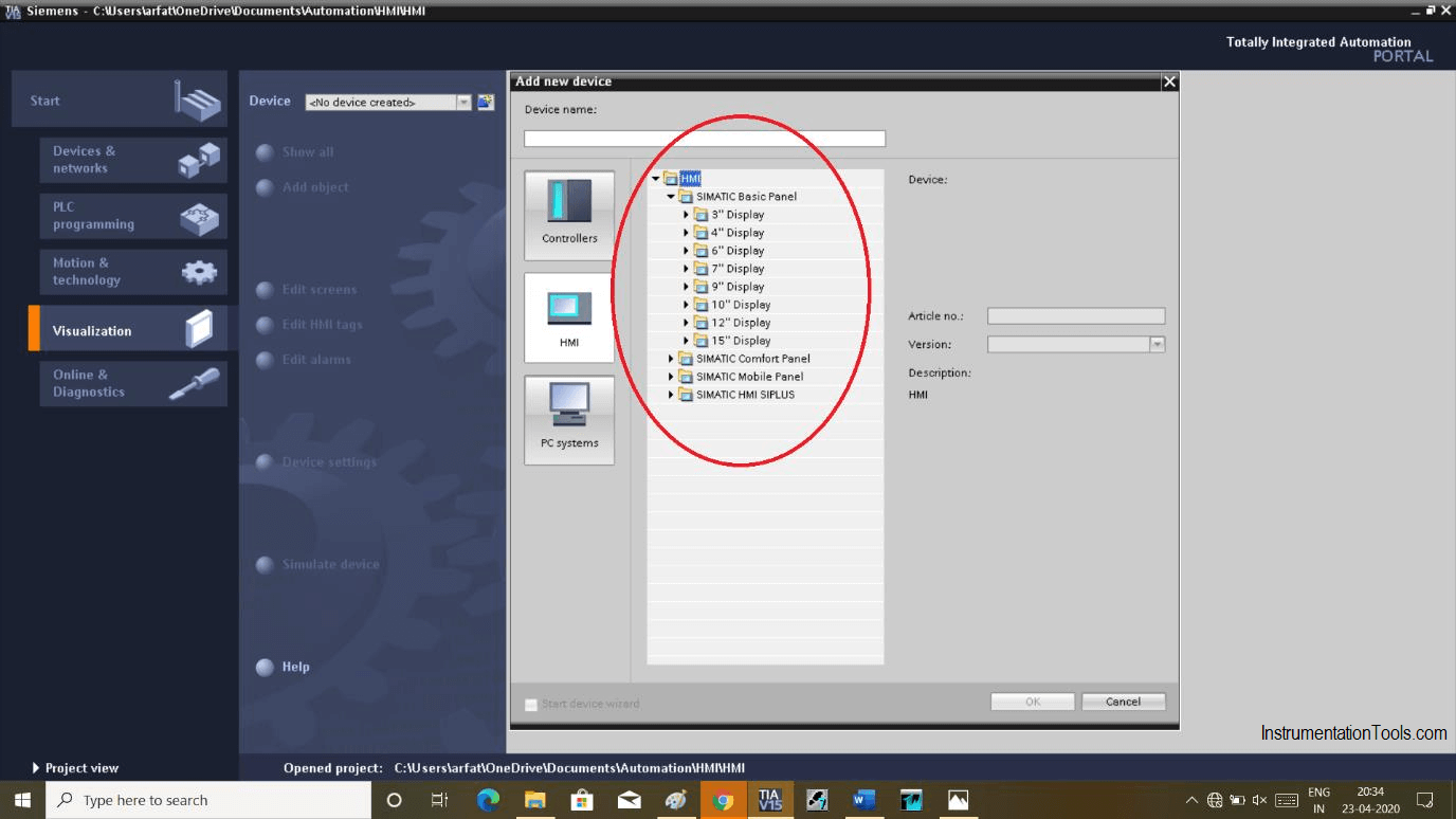
Add new device and then select HMI

Step 4:

Here, you will get a set of the selection, choose the one you want as per application or for learning purposes.
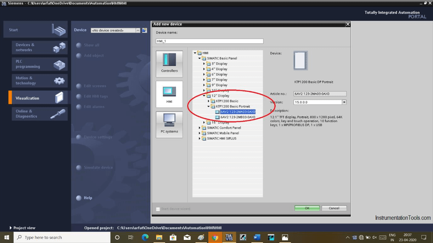
Simatic Basic Panel

Step 5:

Here, I have chosen 12” of the display with the following shown order number.
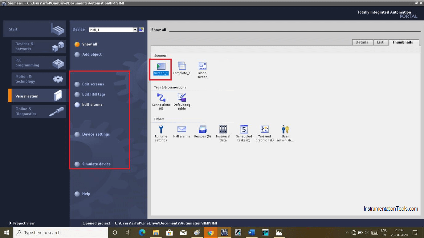
Simatic HMI Configuration

Step 6:

After hitting “ok” the following window will appear. Here, on the left-hand side, you get a selection to edit HMI screens and alarm.

On the right-hand side, you can see many options from where you can create password protection, alarms, recipe, historical data, etc.

Double click on “screen_1” to enter in visualization environment.
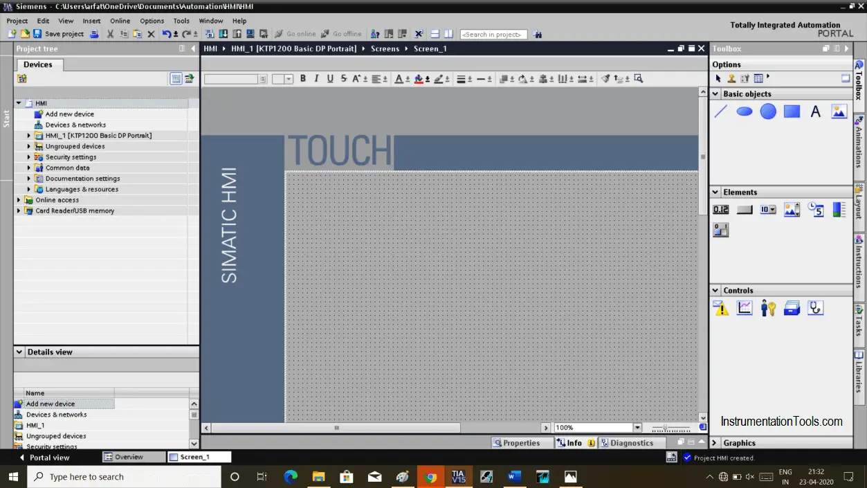
Siemens visualization environment

Step 7:

Clicking on the screen will appear following the window. As per our selection of 12” of the display, it will show the display of the same size.

To access the full area of the screen you can zoom out the screen by reducing the amount the percentage.
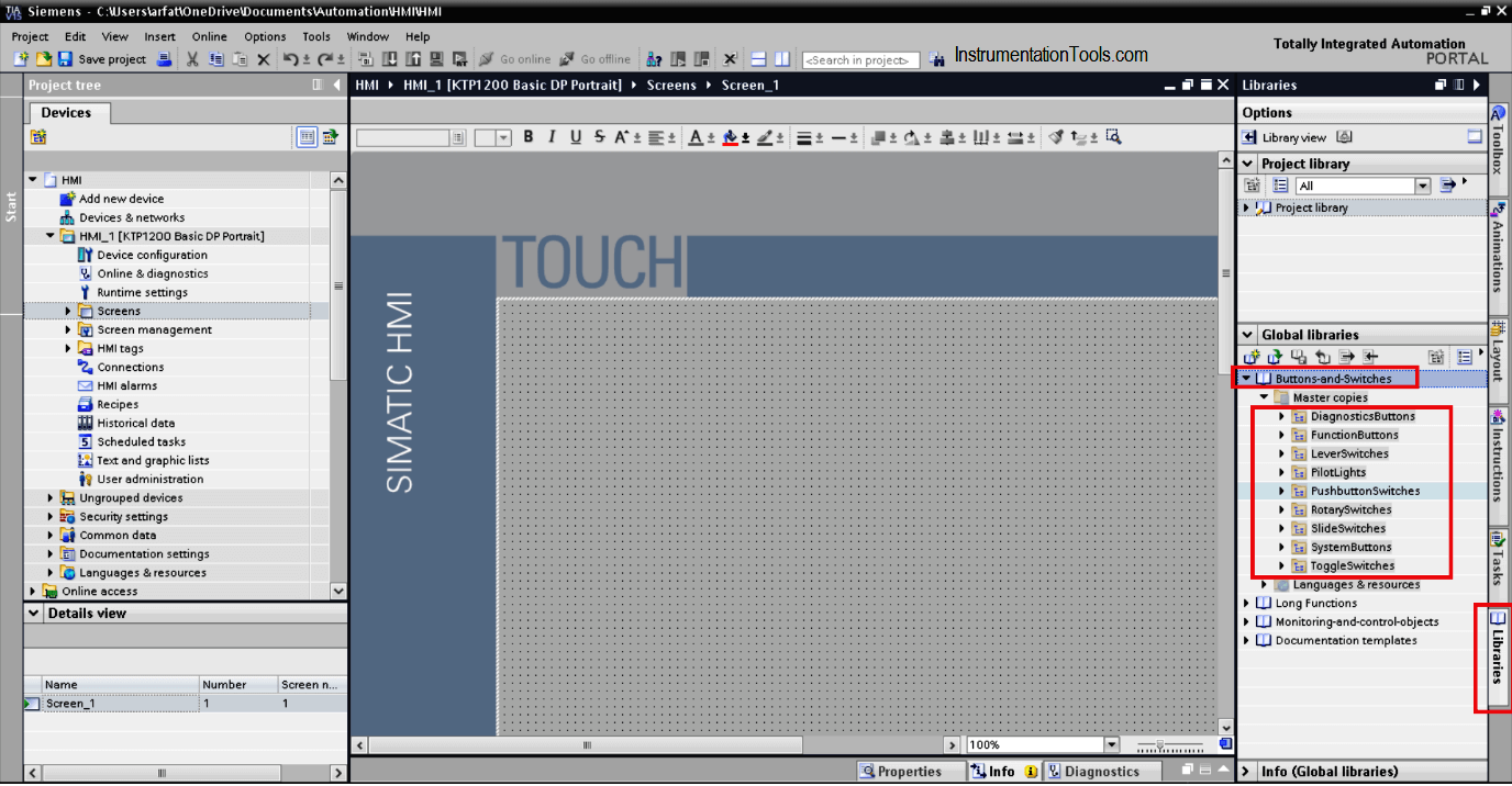
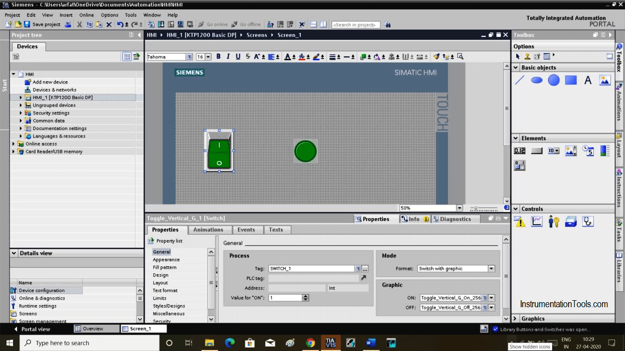
Simatic HMI

Step 8:

To add pushbutton and pilot lights or other elements, select “Library” on the bottom right side then select “button and switches”

add pushbutton and pilot lights in HMI Screen

Step 9:

Let’s create a switch and lamp to understand with an example. To create a switch and lamp, select “Library” and choose as shown in the above window.

To give tag name double click on “switch” and give a name in our case” SWITCH_1”. Now double click on the lamp and give the same name as “SWITCH_1” to make it turn on.
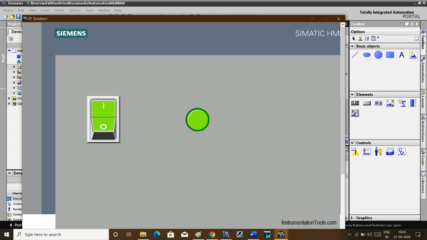
Configure Switch and Lamp in HMI Screen

Step 10:

Select the “simulation” icon to enter in a simulation environment.

Simulation icon in HMI Software

Step 11:

In the simulation window, turning on switch will turn on the lamp.

Create an Application in HMI using Tia Portal

Author: Suhel Patel

If you liked this article, then please subscribe to our YouTube Channel for PLC and SCADA video tutorials.

You can also follow us on Facebook and Twitter to receive daily updates.

Read Next:

  • Force PLC Inputs & Outputs
  • Wonderware Intouch HMI
  • HMI Health Checks Procedure
  • Siemens PLC Simulator
  • Free HMI Software Download
Don't Miss Our Updates
Be the first to get exclusive content straight to your email.
We promise not to spam you. You can unsubscribe at any time.
Invalid email address
You've successfully subscribed !

Continue Reading

Industrial Automation Pre-Engineering Design Documents – Project & Process
Micro Memory Card (MMC) in Siemens PLC
Why is 24 Volts Commonly used in PLC Systems?
Auto Sugar Bag Filling Station
PLC based Automatic Packaging System
XG5000 Example of Simple Conveyor Control PLC Program
Share This Article
Facebook Whatsapp Whatsapp LinkedIn Copy Link
Share
Leave a Comment

Leave a Reply Cancel reply

Your email address will not be published. Required fields are marked *

Stay Connected

128.3kFollowersLike
69.1kFollowersFollow
210kSubscribersSubscribe
38kFollowersFollow

Categories

Explore More

#15 PLC Best Practices – Safe State when PLC Restarts
Auto Tiffin Box Filling Station
Documentation and Change Control of PLC or DCS Systems
How to Use ModScan Software for Testing Modbus Communication?
PLC Ladder Logic for Opposite Acting Control Valves Application
Ferrules and Cross Ferruling
Real-time PLC Projects – Industrial Automation
How a PLC do the Scaling for a Sensor ?

Keep Learning

Micro PLC

Micro PLC Hardware Configuration

PLC Program to Control Level of Series Tanks

Series Tanks Level Control using PLC Ladder Programming

Light Tower in Industrial Automation

What is a Tower Lamp? – Light Tower in Industrial Automation

TON Timer in RSlogix

Why is RTO used in the Place of TON Timer?

PLC Program for Filling Operation

PLC Program for Continuous Filling Operation

PLC Program for Automatic Bottle Rejection System

PLC Program for Automatic Bottle Rejection System

Latching and Unlatching in PLC Programming for Beginners

Latching and Unlatching in PLC Programming Example

Electrical Ladder Diagram Control using Timers Example

Electrical Ladder Diagram Control using Timers Example

Learn More

What happen When Synchronous Generator loss Excitation

Power Electronics Objective Questions

Inverters Quality Objective Questions

Configuration of Siemens Scada and PLC

#12 PLC Best Practices – Validate Inputs based on Physical Plausibility

Various Types of Sensors Used in Water Treatment Plant

Various Types of Sensors used in Water Treatment Plant

Needle Valve Body Design

What is Needle Valve ?

Analog Modulators Objective Questions

Analog Modulators Objective Questions

Creepage Distance for Insulators in Substation

Creepage Distance for Insulators in Substation

Safety in Automation Systems

Safety in Automation Systems

Menu

  • About
  • Privacy Policy
  • Copyright

Quick Links

  • Learn PLC
  • Helping Hand
  • Part Time Job

YouTube Subscribe

Follow US
All rights reserved. Reproduction in whole or in part without written permission is prohibited.
Welcome Back!

Sign in to your account

Username or Email Address
Password

Lost your password?