Inst ToolsInst ToolsInst Tools
  • Courses
  • Automation
    • PLC
    • Control System
    • Safety System
    • Communication
    • Fire & Gas System
  • Instrumentation
    • Design
    • Pressure
    • Temperature
    • Flow
    • Level
    • Vibration
    • Analyzer
    • Control Valve
    • Switch
    • Calibration
    • Erection & Commissioning
  • Interview
    • Instrumentation
    • Electrical
    • Electronics
    • Practical
  • Q&A
    • Instrumentation
    • Control System
    • Electrical
    • Electronics
    • Analog Electronics
    • Digital Electronics
    • Power Electronics
    • Microprocessor
  • Request
Search
  • Books
  • Software
  • Projects
  • Process
  • Tools
  • Basics
  • Formula
  • Power Plant
  • Root Cause Analysis
  • Electrical Basics
  • Animation
  • Standards
  • 4-20 mA Course
  • Siemens PLC Course
Reading: PLC Application for Stamping Operation – Example Programming
Share
Notification Show More
Font ResizerAa
Inst ToolsInst Tools
Font ResizerAa
  • Courses
  • Design
  • PLC
  • Interview
  • Control System
Search
  • Courses
  • Automation
    • PLC
    • Control System
    • Safety System
    • Communication
    • Fire & Gas System
  • Instrumentation
    • Design
    • Pressure
    • Temperature
    • Flow
    • Level
    • Vibration
    • Analyzer
    • Control Valve
    • Switch
    • Calibration
    • Erection & Commissioning
  • Interview
    • Instrumentation
    • Electrical
    • Electronics
    • Practical
  • Q&A
    • Instrumentation
    • Control System
    • Electrical
    • Electronics
    • Analog Electronics
    • Digital Electronics
    • Power Electronics
    • Microprocessor
  • Request
Follow US
All rights reserved. Reproduction in whole or in part without written permission is prohibited.
Inst Tools > Blog > PLC Tutorials > PLC Application for Stamping Operation – Example Programming

PLC Application for Stamping Operation – Example Programming

This is Programmable Logic Control (PLC) Application for PLC Stamping Operation. Write a PLC program for this process.

Last updated: November 3, 2023 2:34 pm
Editorial Staff
PLC Tutorials
No Comments
Share
5 Min Read
SHARE

This is Programmable Logic Control (PLC) Application for PLC Stamping Operation.

Contents
PLC Stamping OperationProblem DiagramProblem SolutionInputs & Outputs ListPLC Program to Operate Stamping of PartsProgram Description

PLC Stamping Operation

Problem Description

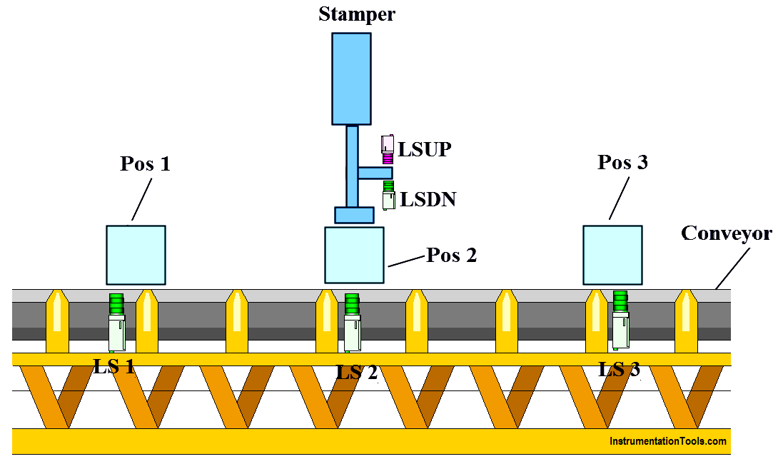
When part is placed on conveyor at position 1, and when cycle start button is pressed it moves to position 2. After reaching at position 2 it will stop for stamping process.

After stamping process part will go at position 3 and from here it will be taken away from conveyor manually.

Write PLC program for this process using ladder diagram language.

Problem Diagram
PLC Program to Operate Stamping of Parts
Problem Solution

In this system, we will use S7-300 PLC and TIA portal software for programming.

Here consider one conveyor system that will move the part from one position to another position.

Three limit switches are used to sense the position of the part on the conveyor. For position 1, 2, and 3 as shown as LS1, LS2, and LS3 respectively.

A reversible motor is used for UP_motor coil for reverse direction and DN_coil for forward direction.

LSDN and LSUP limits switches are used to detect the stamper arm down and up position.

Inputs & Outputs List

Inputs List

  • START PB :- I0.0
  • STOP PB :- I0.1
  • Limit switch for position 1 :- I0.2
  • Limit switch for position 2 :- I0.3
  • Limit switch for position 3 :- I0.4
  • Limit switch to detect upper position :- I0.5
  • Limit switch to detect down position :- I0.6

Outputs List

  • UP_motor :- Q0.1
  • DN_motor :- Q0.2
  • Conveyor motor :- Q0.0

M memory

  • Relay coil :- M0.0
  • Relay coil 1 :- M0.1
  • Relay coil 2 :- M0.2
  • Relay coil 3 :- M0.3
  • Relay coil 4 :- M0.4

PLC Program to Operate Stamping of Parts

PLC Ladder Logic for Stamping Control
PLC Stamping
limit switch for position
PLC Stamping Operation
Stamping PLC Logic
PLC Stamping Application
PLC Stamping Example
PLC Conveyor Stamping

Program Description

For this application, we used S7-300 PLC and TIA portal software for programming.

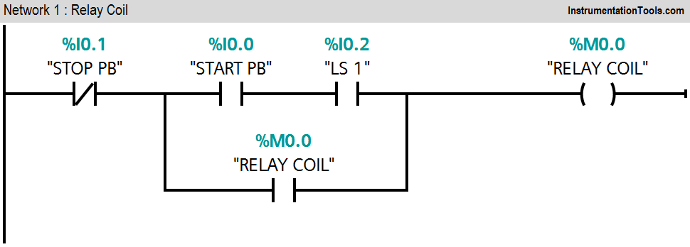
Network 1:

If LS1 (I0.2) is detected and START PB is pressed (I0.0), internal relay coil will be ON. Here cycle will start from home position and we consider here LS1 detection is home position.

Network 2:

If both LS2 (I0.3) and LS3 (I0.4) are not detected, relay coil 1 (M0.0) will be ON.

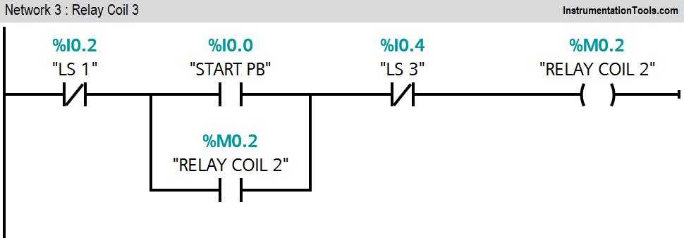
Network 3:

If LS 1 (I0.2) is not detected and START button (I0.0) is pressed, relay coil 2(M0.1) will be ON.

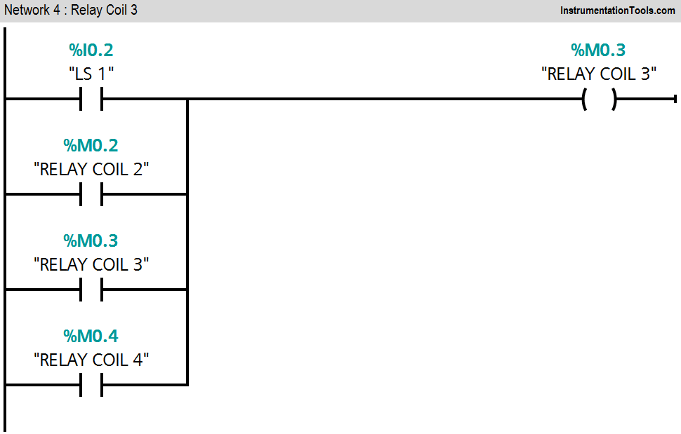
Network 4:

If anyone is detected from LS1 (I0.2), relay coil 2(M0.2) or relay coil 4(M0.4), relay coil 3(M0.3) will be latched.

Network 5:

If relay coil 3(M0.4) is ON and LSUP (I0.5) is not detected, the motor will start reverse (stamping arm moves upper direction).

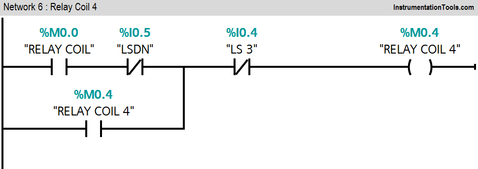
Network 6:

Relay coil 4(M0.4) will start when LSDN (I0.6) and LS 3(I0.4) are not detected.

Network 7:

When LS 2(I0.3) is detected, the stamping process should start so the stamping arm will start to move forward (Q0.2).

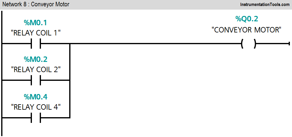
Network 8:

The conveyor motor (Q0.0) will remain in ON condition if relays 1, 2, or 3 are detected.

Here consider UP motor output meaning is stamping arm moves reverse and DN motor output meaning is stamping arm moves forward.

Relay coil, 1, 2, 3, and 4 taken for logical conditions.

Note:- Above application may be different from actual application. This example is only for explanation purpose only. We can implement this logic in other PLC also. This is the simple concept of stamping of parts in industry, we can use this concept in other examples also.

All parameters considered in example are for explanation purpose only, parameters may be different in actual applications. Also all interlocks are not considered in the application.

Author: Bhavesh

If you liked this article, then please subscribe to our YouTube Channel for PLC and SCADA video tutorials.

You can also follow us on Facebook and Twitter to receive daily updates.

Read Next:

  • SR Flip Flop using PLC
  • PLC D Flip Flop using PLC
  • PLC Interview Questions
  • Siemens S7 1200 PLC configuration
Don't Miss Our Updates
Be the first to get exclusive content straight to your email.
We promise not to spam you. You can unsubscribe at any time.
Invalid email address
You've successfully subscribed !

Continue Reading

Quiz Program Logic Using PLC Programming
How to Interchange ON Delay Timer and OFF Delay Timer in a PLC
AI, AO, DI, DO Questions (PLC I/O Types)
How to Choose a PLC for New Project? – Criteria for Selection of PLC
Operator Interface for SCADA System
Difference Between CompactLogix and ControlLogix
Share This Article
Facebook Whatsapp Whatsapp LinkedIn Copy Link
Share
Leave a Comment

Leave a Reply Cancel reply

Your email address will not be published. Required fields are marked *

Stay Connected

128.3kFollowersLike
69.1kFollowersFollow
210kSubscribersSubscribe
38kFollowersFollow

Categories

Explore More

PLC Motor Logic with START, STOP, TEST Push buttons
PLC Timer Instructions
Failsafe Wiring Practices
Speed Control of Pneumatic Cylinder (Explanation with PLC)
PLC Alarm and Trip Documentation
Electrical Earthing Calculations
RSLogix 5000 PLC Programming Procedure
Instrumentation and Control Project Packages – Detail Engineering

Keep Learning

PLC Training Course

#17 PLC Best Practices – Log PLC Uptime and Trend it on HMI

Introduction to SCADA

Types of Interrupts Organization Blocks in Tia Portal

Types of Interrupt OB in Siemens Tia Portal

PLC Programming for Level Switches

PLC Programming using Level Switches

Motor Library in Studio 5000 PLC

Create User-Defined Data Types and Function Blocks in Studio 5000

PLC Program for Star Delta Starter using Functional Block Diagram

PLC Program for Star Delta Starter using Functional Block Diagram

Studio 5000 Define Program or Operator Control in Functional Block Diagram

Studio 5000: Define Program or Operator Control in Functional Block Diagram

PLC Sequence Programming Ladder Logic

PLC Sequence Programming Ladder Logic

Learn More

Profibus network

How Profibus Communication Works

Transformer voltage and turns ratio

Transformer Voltage Ratio

Most Common Types of Cyber Attacks

20 Most Common Types of Cyber Attacks

Transformers Questions and Answers

Latest Transformers Questions and Answers

Surge Protection for the Fieldbus System

PLC Programming Example for a Batch Process

PLC Programming Example for a Batch Process

Voting Logic in Safety Instrumented System (SIS)

Voting Logic in Safety Instrumented System (SIS)

Types of Tank Gauging Level Measurement Systems

Types of Tank Gauging Level Measurement Systems

Menu

  • About
  • Privacy Policy
  • Copyright

Quick Links

  • Learn PLC
  • Helping Hand
  • Part Time Job

YouTube Subscribe

Follow US
All rights reserved. Reproduction in whole or in part without written permission is prohibited.
Welcome Back!

Sign in to your account

Username or Email Address
Password

Lost your password?