A “discrete” data point is one with only two states on and off. Process switches, push-button switches, limit switches, and proximity switches are all examples of discrete sensing devices.
In order for a PLC to be aware of a discrete sensor’s state, it must receive a signal from the sensor through a discrete input channel.
Inside each discrete input module is (typically) a set of light-emitting diodes (LEDs) which will be energized when the corresponding sensing device turns on.
Light from each LED shines on a photo-sensitive device such as a photo-transistor inside the module, which in turn activates a bit (a single element of digital data) inside the PLC’s memory.
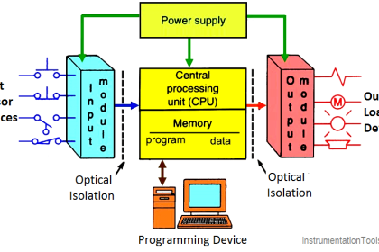
This opto-coupled arrangement makes each input channel of a PLC rather rugged, capable of isolating the sensitive computer circuitry of the PLC from transient voltage “spikes” and other electrical phenomena capable of causing damage:

The internal schematic diagram for a discrete input module (“card”) shown above reveals the componentry typical for a single input channel on that card.
Each input channel has its own optocoupler, writing to its own unique memory register bit inside the PLC’s memory. Discrete input cards for PLCs typically have 4, 8, 16, or 32 channels.
Indicator lamps, solenoid valves, and motor starters (assemblies consisting of contactors and overload protection devices) are all examples of discrete control devices.
In a manner similar to discrete inputs, a PLC connects to any number of different discrete final control devices through a discrete output channel (Note1).
Discrete output modules typically use the same form of opto-isolation to allow the PLC’s computer circuitry to send electrical power to loads: the internal PLC circuitry driving an LED which then activates some form of photosensitive switching device.
Alternatively, small electromechanical relays may be used in lieu of opto-isolating semiconductor switching elements such as transistors (DC) or TRIACs (AC):
Also Check : PLC Input/Output Modules
Note 1 : I/O “channels” are often referred to as “points” in industry lingo. Thus, a “32-point input card” refers to an input circuit with 32 separate channels through which to receive signals from on/off switches and sensors.

As with the schematic diagram for a discrete input module shown previously, the schematic diagram shown here for a discrete output module reveals the componentry typical for a single channel on that card.
Each output channel has its own optocoupler, driven by its own unique memory register bit inside the PLC’s memory. Discrete output cards for PLCs also typically have 4, 8, 16, or 32 channels.
An important concept to master when working with DC discrete I/O is the distinction between current-sourcing and current-sinking devices.
The terms “sourcing” and “sinking” refer to the direction of current (as denoted by conventional flow notation) into or out of a device’s control wire (Note2).
A device sending (conventional flow) current out of its control terminal to some other device(s) is said to be sourcing current, while a device accepting (conventional flow) current into its control terminal is said to be sinking current.
Note 2 : By “control wire,” I mean the single conductor connecting the I/O card channel to the field device, as opposed to conductors directly common with either the positive or negative lead of the voltage source. If you focus your attention on this one wire, noting the direction of conventional-flow current through it, the task of determining whether a device is sourcing or sinking current becomes much simpler.
To illustrate, the following illustration shows a PLC output channel is sourcing current to an indicator lamp, which is sinking current to ground:

These terms really only make sense when electric current is viewed from the perspective of conventional flow, where the positive terminal of the DC power supply is envisioned to be the “source” of the current, with current finding its way “down” to ground (the negative terminal of the DC power supply).
In every circuit formed by the output channel of a PLC driving a discrete control device, or by a discrete sensing device driving an input channel on a PLC, one element in the circuit must be sourcing current while the other is sinking current.
An engineering colleague of mine has a charming way to describe sourcing and sinking: blowing and sucking. A device that sources current to another “blows” current toward the other device.
A device that sinks current “sucks” current from the other device. Many students seem to find these terms helpful in first mastering the distinction between sourcing and sinking despite (or perhaps because of!) their informal nature.
Also Check : PLC Interconnecting Relays
If the discrete device connecting to the PLC is not polarity-sensitive, either type of PLC I/O module will suffice.
For example, the following diagrams show a mechanical limit switch connecting to a sinking PLC input and to a sourcing PLC input:

Note the differences in polarity and labeling between the sinking card’s common terminal and the sourcing card’s common terminal.
On the “sinking” card, the input channel terminal is positive while the common (“Com”) terminal is negative.
and on the “sourcing” card, the input channel terminal is negative while the common (“VDC”) terminal is positive.

Some discrete sensing devices are polarity-sensitive, such as electronic proximity sensors containing transistor outputs.
A “sourcing” proximity switch can only interface with a “sinking” PLC input channel, and vice-versa:

In all cases, the “sourcing” device sends current out of its signal terminal while the “sinking” device takes current into its signal terminal.

Two photographs of a DC (sinking) discrete input module for an Allen-Bradley model SLC 500 PLC are shown here: one with the plastic cover closed over the connection terminals, and the other with the plastic cover opened up for viewing the terminals.
A legend on the inside of the cover shows the purpose of each screw terminal: eight input channels (numbered 0 through 7) and two redundant “DC Com” terminals for the negative pole of the DC power supply to connect:

A standard feature found on practically every PLC discrete I/O module is a set of LED indicators visually indicating the status of each bit (discrete channel). On the SLC 500 module, the LEDs appear as a cluster of eight numbered squares near the top of the module.
A photograph of discrete output terminals on another brand of PLC (a Koyo model DL06) shows somewhat different labeling:

Here, each output channel terminal is designated with a letter/number code beginning with the letter “Y”. Several “common” terminals labeled with “C” codes service clusters of output channels.
In this particular case, each “common” terminal is common only to four output channels. With sixteen total output channels on this PLC, this means there are four different “common” terminals. While this may seem somewhat strange (why not just have one “common” terminal for all sixteen output channels?), it more readily permits different DC power supplies to service different sets of output channels.
Electrical polarity is not an issue with AC discrete I/O, since the polarity of AC reverses periodically anyway. However, there is still the matter of whether the “common” terminal on a discrete PLC module will connect to the neutral (grounded) or hot (ungrounded) AC power conductor.
Also Read : Motor Control Circuits
The next photograph shows a discrete AC output module for an Allen-Bradley SLC 500 PLC, using TRIACs as power switching devices rather than transistors as is customary with DC discrete output modules:

This particular eight-channel module provides two sets of TRIACs for switching power to AC loads, each set of four TRIACs receiving AC power from a “hot” terminal (VAC 1 or VAC 2), the other side of the load device being connected to the “neutral” (grounded) conductor of the AC power source.
Fortunately, the hardware reference manual supplied by the manufacturer of every PLC shows diagrams illustrating how to connect discrete input and output channels to field devices. One should always consult these diagrams before connecting devices to the I/O points of a PLC!
Credits : by Tony R. Kuphaldt – Creative Commons Attribution 4.0 License
PLC Tutorials :
What is Programmable Logic Controller ?
What is Ladder Diagram Programming ?
History of Programmable Logic Controllers
Mis-conceptions of PLC Ladder Logic
Contacts and coils in PLC
Digital Input and Output Modules
Analog I/O and Network I/O
PLC Input/Output Modules
Memory Mapping in PLC
Analog Input Scaling
PLC Example with Switches
Counter Instructions
Timer Instructions
Math instructions
Data Instructions
Ladder Logic Questions
If you liked this article, then please subscribe to our YouTube Channel for PLC and SCADA video tutorials.
You can also follow us on Facebook and Twitter to receive daily updates.


please help me with the loop power and self power connection for analog input module.
Very informational and contentful. Helped me with my research work.
Excellent
Thank You for explaining the functionality of IO modules in a manner that easy to understand for someone who may not have a formal education in electronics ! If you can please share your knowledge on the failure modes of input and output modules in a separate article or email, that would be much appreciated!
Thank sir many notes I didn’t not understand when my teacher teached but to you I understood sir