Now we are discussing about How a PLC Motor Control ?. Before going into the article, let us assume some conditions here.
A PLC has to start a Motor when the Start button is pressed. It has three interlocks which are Motor Vibration High, Overload & Motor Temperature High.
if any of the interlock activated then PLC has to stop the motor immediately.
PLC has to stop the motor if the stop button is pressed.
PLC trip logic or interlock has to be enable only when motor is in Remote mode.
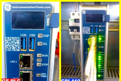
PLC Motor Control

In above figure : Red LED indicator lights on the input and output cards of the PLC indicate if those respective I/O channels are energized.
Note :
- In above figure, Local Control Panel signals are not shown. Local control panel is connected to motor feeder directly.
- 24v DC power directly connected ( in general fuses or barriers will be used, power will be distributed through bus bar)
PLC Inputs
- Start push button
- Stop push button
- Vibration High
- Temperature High
- Overload Trip
- Run feedback
- Local/Remote status
PLC Outputs
- Start Command (Remote Start)
- Stop Command (Remote Stop)
- Start Permissive ( Optional)
The motor is a three phase, 415V AC powered device. So by default high voltage equipment will be powered from substations or motor control centers (MCC) which are maintained by electrical.
So we consider this motor is connected to a simple motor feeder in the substation.
Generally the motor feeder have inputs from field (local control panel) & PLC also. Which are shown in below figure.

Note : the motor feeder may have start, stop, some other trips indications like overload etc… in the motor feeder panel which are not shown in the fig. These are mounted on the motor feeder panel (in addition to LCP).
If motor feeder receives start & stop command inputs from PLC then we call them as Remote Start & Remote Stop signals.
Similarly if motor feeder receives start & stop command inputs from local control panel (LCP) which is installed in field (near to motor) then we call them as Local Start & Local Stop signals.
In common practice, this LCP has emergency stop & Local/Remote selection switch also.
The motor feeder also sends a Local/Remote status to PLC. If Local/Remote selection switch is in Local mode then motor feeder will only consider signals from LCP and ignore the commands from PLC.
Similarly if Local/Remote Selection switch in Remote Mode then motor feeder will consider signals from Remote i.e. PLC and ignore the signals from LCP.
For example : if Local/Remote selection Switch in Remote Mode. If field operator pressed the start push button from the field LCP then motor will not be started as the selection is in remote mode.
Depends on the Local/Remote selection switch status the motor feeder will decides which signals to be consider i.e. either PLC or LCP signals.
Note : Local/Remote Selection will not be applied for Emergency Stop or Stop Commands either from PLC or LCP. Whatever mode it is, the Stop commands will be accepted by motor feeder and stops the motor immediately. This is a safety concern.
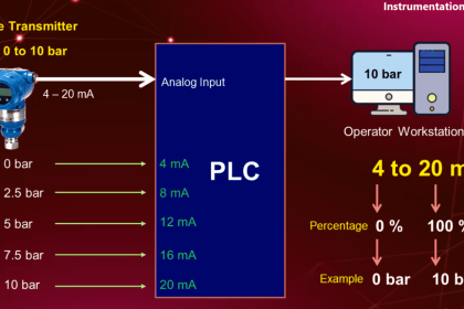
Also Read : How a 4-20mA Transmitter Works ?
Lets see how a PLC controls a motor.
Now Local/Remote selection switch is in Remote mode.
Here we are sending an Permissive signal ( Start Permissive) to the motor feeder. For starting the motor, the permissive must be healthy otherwise motor feeder will be de-energized or will not start the motor.
In PLC, Start permissive will be used as a extra safety & for checking the interlock status. if all the interlocks are healthy then only permissive signal will be sent to motor feeder.
Generally we call this as “Start Permissive”, as name implies it is only required for starting the motor, after motor started the status of this permissive signal will not be considered by motor feeder (Only required for starting the motor).
This is an optional signal. For High capacity motors, start permissive signals will be used. For normal or low capacity motors these are very rarely used, again depends on our applications, industry, requirements etc.
Lets say all interlocks are healthy, so PLC sends the permissive signal to motor feeder.
Now start push button is pressed.
First PLC checks the Local/Remote status, if it is in Remote then proceeds further.
Again it checks for any active trips/interlocks. If there is no interlock or all working normal, then PLC sends a start command to substation where motor feeder is installed.
In this example we have three interlocks: Motor Vibration High, Motor Temperature High & Overload trip.
In generally High capacity motors are equipped with Vibration sensors & temperature sensors.
In our example we consider vibration signals as fail safe, so default status is normally closed, if high vibration appears then the contact become Normally Open & PLC trips/stops the motor.
We have another interlock which is Overload trip, this input is taken from the motor feeder. The temperature sensors signal is normally open and when temperature high then it becomes normally close and PLC trips/Stops the motor.
Note: Fail safe or default contact status either NC or NO are depends on our application or logic requirements. Here we are only discussing an example for understanding the concept.
After receiving the start command from the PLC, motor feeder will be energized and power up the motor. After motor started, the motor feeder will send the Run feedback to the PLC. The run feedback will be displayed on the graphics.
In some PLC’s or in safety PLC’s if the Run feedback is not received in specified time frame ( say within 5 seconds) then PLC automatically sends an Stop signals to the motor feeder. This is a optional feature in normal PLC applications( must in safety PLC’s).
Say now Vibration High came, then PLC sends a stop command to motor feeder and it immediately stops the motor. The run feedback status also updates accordingly.
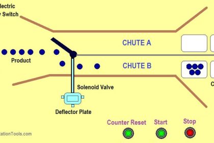
Example Video :
Motor will be started when Level Transmitter will be High & again it will stopped at Level Transmitter Low
Start Permissive signal not used in the below video.
Abbreviations :
- MCC : Motor Control Center or Substation where motor will be powered.
- PLC/DCS : Control System, where Motor can be controlled as per logic (Auto) or as per operator action (Manual).
- LCP : Local Control Panel which is installed in the field, near motor in which start, stop push buttons are available
PLC Tutorials :
What is Programmable Logic Controller ?
What is Ladder Diagram Programming ?
History of Programmable Logic Controllers
Mis-conceptions of PLC Ladder Logic
Contacts and coils in PLC
Digital Input and Output Modules
Analog I/O and Network I/O
PLC Input/Output Modules
Memory Mapping in PLC
Analog Input Scaling
PLC Example with Switches
Counter Instructions
Timer Instructions
Math instructions
Data Instructions
Ladder Logic Questions
If you liked this article, then please subscribe to our YouTube Channel for PLC and SCADA video tutorials.
You can also follow us on Facebook and Twitter to receive daily updates.


Excellent Article sir. I am a fresher in Instrumentation Field. Really helpful. Thanks a lot. Best website for Instrumentation Engineers.
Super articals sir,very useful
Its been a super simple way to understand the content
Melhor site de instrumentação!! Obrigado por compartilha esses artigos!! eu estou estudando cada artigos que é postado aqui..
Translated : Portuguese to English : Best instrumentation site !! Thanks for sharing those articles !! I am studying every article that is posted here ..
thank u so much sir your this website is very nice and good for instrument technician but pls sir give option for save bcoz we can read online no can b saved ao pls give option for save
Very good presentation
I need more knowledge loop diagram
I need more knowledge on motor connections and motor speed control.
Appreciate for this free contents which are very useful. Myself from Operations & found these very informative & has increased my insight on Instrumentation & systems. Thanks you very much.
Thank you very much for your time and knowledge you have given us.
I have learnt much from this. Stay blessed
This article is so well articulated that if you don’t understand then you were just read like a story book not studying.
Hi sir my name is m jagadish i want to contact you about the plc ladder programming i didnt get your number so it is my number please call me sir 7989001943
I need help on this assignment.
Draw a ladder diagram for the given situation.
An audible alarm is given if the motor trips due to an overload. The motor runs if pressure is low and stops if there is overload and pressure is above limit. A signal lamp is required to be switched on if a pump is running and the pressure is satisfactory or the lamp test switch is closed.