Inst ToolsInst ToolsInst Tools
  • Courses
  • Automation
    • PLC
    • Control System
    • Safety System
    • Communication
    • Fire & Gas System
  • Instrumentation
    • Design
    • Pressure
    • Temperature
    • Flow
    • Level
    • Vibration
    • Analyzer
    • Control Valve
    • Switch
    • Calibration
    • Erection & Commissioning
  • Interview
    • Instrumentation
    • Electrical
    • Electronics
    • Practical
  • Q&A
    • Instrumentation
    • Control System
    • Electrical
    • Electronics
    • Analog Electronics
    • Digital Electronics
    • Power Electronics
    • Microprocessor
  • Request
Search
  • Books
  • Software
  • Projects
  • Process
  • Tools
  • Basics
  • Formula
  • Power Plant
  • Root Cause Analysis
  • Electrical Basics
  • Animation
  • Standards
  • 4-20 mA Course
  • Siemens PLC Course
Reading: PLC Example with Switches
Share
Notification Show More
Font ResizerAa
Inst ToolsInst Tools
Font ResizerAa
  • Courses
  • Design
  • PLC
  • Interview
  • Control System
Search
  • Courses
  • Automation
    • PLC
    • Control System
    • Safety System
    • Communication
    • Fire & Gas System
  • Instrumentation
    • Design
    • Pressure
    • Temperature
    • Flow
    • Level
    • Vibration
    • Analyzer
    • Control Valve
    • Switch
    • Calibration
    • Erection & Commissioning
  • Interview
    • Instrumentation
    • Electrical
    • Electronics
    • Practical
  • Q&A
    • Instrumentation
    • Control System
    • Electrical
    • Electronics
    • Analog Electronics
    • Digital Electronics
    • Power Electronics
    • Microprocessor
  • Request
Follow US
All rights reserved. Reproduction in whole or in part without written permission is prohibited.
Inst Tools > Blog > PLC Tutorials > PLC Example with Switches

PLC Example with Switches

Last updated: March 4, 2021 4:26 pm
Editorial Staff
PLC Tutorials Switches
3 Comments
Share
4 Min Read
SHARE

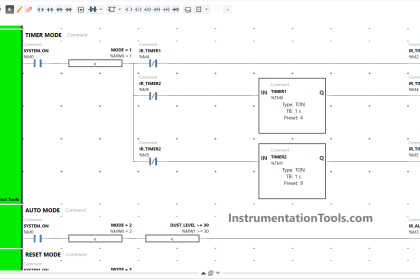
For example, the LED in this circuit will turn on if the liquid level rises above 14 inches and the pressure falls below 22 PSI and either the flow is less than 3 gallons per minute or the temperature is greater than 125 degrees Fahrenheit:

PLC Example with Switches

Switch Relay Schematic

Since we know we need a switch to be closed in order to conduct electricity and provide a path for current in this circuit, we are looking for the necessary conditions to close each switch.

For any normally-closed (NC) switch, this means a stimulus value less than the actuation threshold.

For any normally-open (NO) switch, this means a stimulus value great enough to exceed the threshold and “hold” the switch in its actuated state.

The flow and pressure switches in this circuit are both NC, we are looking for flow and pressure values less than the respective settings.

Since the level and temperature switches are both NO, we are looking for level and temperature values in excess of their respective settings.

Also Read : Basics of Switches

The present status of a switch may be determined by comparing its stimulating quantity against its trip (threshold) setting.

A switch will be in its “normal” (resting) state when the stimulus value is less than the threshold value. Conversely, a switch will be in its “actuated” state when the stimulus value exceeds the threshold value.

Determination of a switch’s status, therefore, is a matter of comparing the stimulus quantity to the threshold “trip” setting.

One cannot simply look at the schematic diagram to tell what the switch is doing – one must compare the switch’s setting versus against a known stimulus value in order to tell whether it will be in its resting state or not.

Likewise, if we happen to know the switch’s present status in a system, we may qualitatively determine the stimulating quantity by comparing the present status against the “normal” (resting) status.

If a switch is in its resting state, then the stimulating quantity must be less than the trip threshold. If a switch is in its actuated (non-normal) state, then the stimulating quantity must be greater than the trip threshold.

The next example showcases these determinations.

In this next example, we see a pictorial representation of multiple switches wired to the discrete input channels of a programmable logic controller (PLC), with red LED indicators denoting the real-time status of each input on the PLC:

PLC Example with Switches

We may determine a switch’s degree of stimulation by comparing its present status with its “normal” status.

If a switch happens to be in the same state as its normal state (i.e. resting), we know its stimulus must be less than the threshold (trip) value.

Consider, If a switch happens to be in the opposite state as its normal state (i.e. actuated), we know its stimulus has exceeded the threshold (trip) value. The states of these four switches may be shown in a table:

Status of Switches

If you liked this article, then please subscribe to our YouTube Channel for PLC and SCADA video tutorials.

You can also follow us on Facebook and Twitter to receive daily updates.

Read Next:

PLC Star Delta Motor Starter

Ladder Logic Questions & Answers

Basics of Fail-safe Circuits

Siemens PLC Interview Questions

DCS Vs PLC Architecture

Don't Miss Our Updates
Be the first to get exclusive content straight to your email.
We promise not to spam you. You can unsubscribe at any time.
Invalid email address
You've successfully subscribed !

Continue Reading

Set the S5 Timer Value by a Memory Word
What is Contextual HMI? – HMI Screens on a Mobile or Tablet
Motor Stop Interlock for Changing the Direction PLC Program
Microwave Barrier Level Switch Working Principle
PLC Program for Traffic Light Sequence using Functional Blocks
Failsafe Wiring Practices
Share This Article
Facebook Whatsapp Whatsapp LinkedIn Copy Link
Share
3 Comments
  • rvsaradhi says:
    August 14, 2017 at 12:51 pm

    Dear sir,
    please note that as per your micro logic AB plc input cards will provide 24 v dc power supply
    It appears that DI cards does not provide control supply kindly provide correct information
    ISA,org says clearly for switch(setpointfor pressure ,temp switch
    levelswitch,flow switchs)
    it preesumed that industry oriented shall be written insteady of theory
    regards
    saradhi
    9949611107

    Reply
    • S Bharadwaj Reddy says:
      August 15, 2017 at 11:59 am

      Hi, In the example picture, +24v DC power of PLC is used for the switches in the loop. Meaning that we are supplying external power to the DI cards. Generally separate +24v DC bus bar power supply will be looped. i think image to be improved for better understanding. Thank you

      Reply
  • Muhammad Latif says:
    March 19, 2021 at 10:03 pm

    Hi evryone,

    Im biggener in PLC programing. Can anyone plz tell me how to add logic when a motor is running while changing local remote selection motor should not stop.

    Thanks

    Reply

Leave a Reply Cancel reply

Your email address will not be published. Required fields are marked *

Stay Connected

128.3kFollowersLike
69.1kFollowersFollow
210kSubscribersSubscribe
38kFollowersFollow

Categories

Explore More

Instrumentation Earthing
How to Detect Speed of Conveyor in PLC?
Door Lock with Delay PLC Exercise Problems
How a PLC do the Scaling for a Sensor ?
MCQ on PLC (Programmable Logic Controller)
MOVE Instruction in PLC – What You Need to Know?
PLC Timer Instructions
Automate Batch Mixing with Repeated Cycles in Omron PLC

Keep Learning

How to Link SQL With Indusoft Web Studio

How to Use an SQL Server with Indusoft Web Studio?

CODESYS open source PLC software

What is CODESYS? Why Do You Need to Learn it?

Things to Take Care of When Designing SCADA System

Things to Take Care of When Designing SCADA System

PLC Program for Temperature Control using Thermostat

PLC Program for Temperature Control using Thermostat

Understanding Braking Theory in VFD

Understanding Braking Theory in VFD

Top 5 Advantages of Human-Machine Interface (HMI)

Top 5 Advantages of Human-Machine Interface (HMI)

PLC Program using Counters

PLC Counters Program

Analog Inputs in Siemens TIA Portal

What are Analog Inputs? – Analog Signals Processing in PLC

Learn More

Why Fire and Gas Detectors are 3-Wire types instead of 2 Wire

Why Fire and Gas Detectors are 3-Wire types instead of 2 Wire?

Use of Regions in SCL Language

Use of Regions in SCL Language

Counters and Timers Projects Using Analog Electronic Devices

Top 100 Counters and Timers Projects Using Analog Electronic Devices

desuperheater

Concept of Desuperheater

Chemical Reactor Vessel P and ID

Questions on Chemical Reactor Vessel P & ID

Nonlinear Control Systems

Common Physical Nonlinearities

PLC Program to Control Gas Pressure using Closed-Loop

PLC Program to Control Gas Pressure using Closed-Loop

Web Tension Measurement

Web Tension Measurement and Control Technologies

Menu

  • About
  • Privacy Policy
  • Copyright

Quick Links

  • Learn PLC
  • Helping Hand
  • Part Time Job

YouTube Subscribe

Follow US
All rights reserved. Reproduction in whole or in part without written permission is prohibited.
Welcome Back!

Sign in to your account

Username or Email Address
Password

Lost your password?