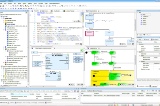
This is the PLC Program for Conditional Logic Circuit. The below example is based on the ladder logic using a programmable logic controller.
PLC Conditional Control Logic
In Industry or plants, there are lots of gearbox systems used for different machines/motors.
For smooth operation of gearbox motors, they need to be lubricated every time because good maintenance work can extend gearbox life.
But the problem is that operators often make mistakes during machine operation because in every gearbox motor mechanism, we need to start lubrication first and then the main gearbox mechanism should start.
So we have to implement a logic to make sure things are properly controlled from a PLC system.
Problem Diagram

Note: For easy discussions, Local/Remote, or any other permissive interlocks are not considered in this example.
Problem Solution
Here we solve this problem by using a simple conditional logic example, in this example, there is one gearbox motor and we need to provide lubrication before starting it.
So for lubrication, we have a lubrication motor (also called as Oil Pump or Auxiliary Lube Oil Pump) and it will provide lubrication oil to the main motor or gearbox motor.
Also, we will provide an interlock system, so the operator cannot start/operate the Main motor directly without using proper lubrication otherwise the main motor may overheat and it may be damaged after some runs without proper care.
The operator has to switch ON oil pump first and then only he can able to operate the main motor.
By using this logic, we can take care of the gearbox motor for a long time run with proper lubrication.
Operators start/stop oil pump by using START and STOP push buttons of oil pump.
Both Oil Pump and Main Motor have separate individual START & STOP push buttons as shown in above diagram.
PLC Inputs List
- Oil Pump StART PB : I0.0
- Oil Pump STOP PB : I0.1
- Main Motor START PB : I0.2
- Main Motor STOP PB : I0.3
PLC Outputs List
- Oil Pump Motor : Q0.0
- Main Motor : Q0.1
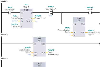
PLC Ladder diagram for conditional Control Circuit

Ladder Logic Description
- In this application, we used Siemens S7-1200 PLC and TIA Portal Software for programming. We can also design this logic with relay circuit.
- This circuit is also known as conditional control circuit because second sequence is depended on first condition.
- We will write logic for oil pump in Network 1. Here we will take NO contact of oil pump START PB (I0.0) and also we have to consider one NO contact of oil pump (Q.0) coil for latching START command.
- Put NC contact of oil pump stop PB (I0.1) in series for unlatching the circuit by pressing oil pump STOP PB (I0.1), so operator can stop the oil pump (Q0.0).
- Now write the logic for main motor in Network 2. Here we will take NO contact of main motor START PB (I0.2) and also take one more NO contact of the main motor coil for latching the main motor (Q0.1).
- Put NC contact of main motor stop PB(I0.3) in series for unlatching the circuit by pressing the main motor STOP PB(I0.3), so operator can stop the main motor(Q0.1).
- Put NO contact of oil pump (Q0.0) in series after the main motor START PB(I0.2) for interlocking. So that operator has to start oil pump (Q0.0) and then only he can START the main motor (Q0.1).
Runtime Test Cases

Note: The above PLC Logic provided for basic idea about application of PLC Program for Conditional Control Logic. The Logic is limited and not complete application.
Author: Bhavesh
If you liked this article, then please subscribe to our YouTube Channel for PLC and SCADA video tutorials.
You can also follow us on Facebook and Twitter to receive daily updates.
Read Next:
- Field Instruments Interview Questions
- PLC Water filling and Discharging Process
- Sequential Motor Control using PLC
- PLC Interview Questions and Answers
- Overview of SCADA System


Dear Sir,
This is not foolproof logic.This is just a interlock with lot of loop holes.
Hi Sharma, I think the Author just explaining a simple example of conditional logic, not designing complete application/logic. Can You please share the loop holes, Thanks.
Dear Sir,
Sorry for inconvenience
This is example for concept explanation of conditional circuit.
It is not complete system.
Simple but effective circuit for easy understanding… Thanxs to you. Bhavesh sir, please share more plc. Logic