Inst ToolsInst ToolsInst Tools
  • Courses
  • Automation
    • PLC
    • Control System
    • Safety System
    • Communication
    • Fire & Gas System
  • Instrumentation
    • Design
    • Pressure
    • Temperature
    • Flow
    • Level
    • Vibration
    • Analyzer
    • Control Valve
    • Switch
    • Calibration
    • Erection & Commissioning
  • Interview
    • Instrumentation
    • Electrical
    • Electronics
    • Practical
  • Q&A
    • Instrumentation
    • Control System
    • Electrical
    • Electronics
    • Analog Electronics
    • Digital Electronics
    • Power Electronics
    • Microprocessor
  • Request
Search
  • Books
  • Software
  • Projects
  • Process
  • Tools
  • Basics
  • Formula
  • Power Plant
  • Root Cause Analysis
  • Electrical Basics
  • Animation
  • Standards
  • 4-20 mA Course
  • Siemens PLC Course
Reading: Basic DC Power Supply Circuit
Share
Notification Show More
Font ResizerAa
Inst ToolsInst Tools
Font ResizerAa
  • Courses
  • Design
  • PLC
  • Interview
  • Control System
Search
  • Courses
  • Automation
    • PLC
    • Control System
    • Safety System
    • Communication
    • Fire & Gas System
  • Instrumentation
    • Design
    • Pressure
    • Temperature
    • Flow
    • Level
    • Vibration
    • Analyzer
    • Control Valve
    • Switch
    • Calibration
    • Erection & Commissioning
  • Interview
    • Instrumentation
    • Electrical
    • Electronics
    • Practical
  • Q&A
    • Instrumentation
    • Control System
    • Electrical
    • Electronics
    • Analog Electronics
    • Digital Electronics
    • Power Electronics
    • Microprocessor
  • Request
Follow US
All rights reserved. Reproduction in whole or in part without written permission is prohibited.
Inst Tools > Blog > Electronic Devices & Circuits > Basic DC Power Supply Circuit

Basic DC Power Supply Circuit

Last updated: December 10, 2019 10:02 am
Editorial Staff
Electronic Devices & Circuits
1 Comment
Share
2 Min Read
SHARE

All active electronic devices require a source of constant dc that can be supplied by a battery or a dc power supply.

The dc power supply converts the standard AC voltage available at wall outlets into a constant dc voltage.

The dc power supply is one of the most common circuits you will find, so it is important to understand how it works.

The voltage produced is used to power all types of electronic circuits including consumer electronics, computers, industrial controllers, and most laboratory instrumentation systems and equipment.

The dc voltage level required depends on the application, but most applications require relatively low voltages.

Basic DC Power Supply Circuit

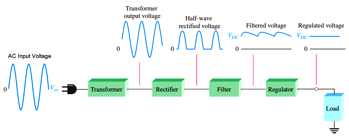
A basic block diagram of the complete power supply is shown in Above Figure.

Generally the ac input line voltage is stepped down to a lower ac voltage with a transformer (although it may be stepped up when higher voltages are needed or there may be no transformer at all in rare instances).

A transformer changes ac voltages based on the turns ratio between the primary and secondary. If the secondary has more turns than the primary, the output voltage across the secondary will be higher and the current will be smaller. If the secondary has fewer turns than the primary, the output voltage across the secondary will be lower and the current will be higher.

The rectifier can be either a half-wave rectifier or a full-wave rectifier. The rectifier converts the ac input voltage to a pulsating dc voltage.

The filter eliminates the fluctuations in the rectified voltage and produces a relatively smooth dc voltage.

The regulator is a circuit that maintains a constant dc voltage for variations in the input line voltage or in the load. Regulators vary from a single semiconductor device to more complex integrated circuits.

The load is a circuit or device connected to the output of the power supply and operates from the power supply voltage and current.

Don't Miss Our Updates
Be the first to get exclusive content straight to your email.
We promise not to spam you. You can unsubscribe at any time.
Invalid email address
You've successfully subscribed !

Continue Reading

Varactor Diode Operation
Seven Segment Display Working Principle
Photodiode as Variable Resistance Device
Comparison of MOSFET and BJT
Basics of Voltage Regulators
Electron Gun of Cathode Ray Tube
Share This Article
Facebook Whatsapp Whatsapp LinkedIn Copy Link
Share
1 Comment
  • M.Tanweer Alam says:
    October 4, 2016 at 2:53 pm

    I want notes regarding testing of I/Os in marshling panel.

    Reply

Leave a Reply Cancel reply

Your email address will not be published. Required fields are marked *

Stay Connected

128.3kFollowersLike
69.1kFollowersFollow
210kSubscribersSubscribe
38kFollowersFollow

Categories

Explore More

Diodes Voltage Tripler
What is Kirchhoff’s Voltage Law
How a PN Junction Formed in a Diode
Ripple Voltage in Rectifiers
Dependent Current Source
Circuit Elements and Types of Circuits
Transistor Base Bias
Zener Diode Breakdown Characteristics

Keep Learning

Why Silicon is preferred over Germanium ?

Why Silicon is preferred over Germanium ?

Diode-testing-with-multimeter

How to Test a Diode using Multimeter

Semiconductors Diodes Questions & Answers

Semiconductors Diodes Questions & Answers

Ideal Diode Characteristics

Ideal Diode Characteristics

Transistor Emitter Feedback Bias

Transistor Emitter Feedback Bias

Combining Independent Current Sources in Parallel

Combining Independent Current Sources in Parallel

Transistor Voltage Divider Bias

Transistor Voltage Divider Bias

diode-limiter-principle

Diode Limiters/Clippers Operation

Learn More

Frequency Response MCQ

Experimentation of Transfer Function

O Ring Failure

How O-Ring Failure caused NASA’s shuttle to Blast ?

Difference Between LED and LDR

Difference Between LED and LDR

CNC Machining Deep Hole Drilling

Deep Hole Drilling Ideal Methods For CNC Machining

MOSFET VI Characteristics

Power MOSFET

Importance of Instrumentation Engineering

Importance of Instrumentation Engineering – Objectives

Transistor Collector Characteristic Curves

Transistor Collector Characteristic Curves

Pressure Transmitter Working Principle

Gage and Absolute Pressure Transmitters Principle

Menu

  • About
  • Privacy Policy
  • Copyright

Quick Links

  • Learn PLC
  • Helping Hand
  • Part Time Job

YouTube Subscribe

Follow US
All rights reserved. Reproduction in whole or in part without written permission is prohibited.
Welcome Back!

Sign in to your account

Username or Email Address
Password

Lost your password?