Inst ToolsInst ToolsInst Tools
  • Courses
  • Automation
    • PLC
    • Control System
    • Safety System
    • Communication
    • Fire & Gas System
  • Instrumentation
    • Design
    • Pressure
    • Temperature
    • Flow
    • Level
    • Vibration
    • Analyzer
    • Control Valve
    • Switch
    • Calibration
    • Erection & Commissioning
  • Interview
    • Instrumentation
    • Electrical
    • Electronics
    • Practical
  • Q&A
    • Instrumentation
    • Control System
    • Electrical
    • Electronics
    • Analog Electronics
    • Digital Electronics
    • Power Electronics
    • Microprocessor
  • Request
Search
  • Books
  • Software
  • Projects
  • Process
  • Tools
  • Basics
  • Formula
  • Power Plant
  • Root Cause Analysis
  • Electrical Basics
  • Animation
  • Standards
  • 4-20 mA Course
  • Siemens PLC Course
Reading: PLC 1 Push Button to Turn ON or OFF 1 Output
Share
Font ResizerAa
Inst ToolsInst Tools
Font ResizerAa
  • Courses
  • Design
  • PLC
  • Interview
  • Control System
Search
  • Courses
  • Automation
    • PLC
    • Control System
    • Safety System
    • Communication
    • Fire & Gas System
  • Instrumentation
    • Design
    • Pressure
    • Temperature
    • Flow
    • Level
    • Vibration
    • Analyzer
    • Control Valve
    • Switch
    • Calibration
    • Erection & Commissioning
  • Interview
    • Instrumentation
    • Electrical
    • Electronics
    • Practical
  • Q&A
    • Instrumentation
    • Control System
    • Electrical
    • Electronics
    • Analog Electronics
    • Digital Electronics
    • Power Electronics
    • Microprocessor
  • Request
Follow US
All rights reserved. Reproduction in whole or in part without written permission is prohibited.
Inst Tools > Blog > PLC Tutorials > PLC 1 Push Button to Turn ON or OFF 1 Output

PLC 1 Push Button to Turn ON or OFF 1 Output

This article explains the programming concept for PLC 1 push button to turn ON or OFF 1 output device.

Last updated: April 4, 2024 3:22 pm
Editorial Staff
PLC Tutorials
No Comments
Share
7 Min Read
SHARE

This article explains the programming concept for the PLC 1 push button to turn ON or OFF 1 output device.

Contents
PLC Push Button ProgramPLC Training VideosInputsOutputMemory Bits1 Push Button to Turn ON or OFF 1 OutputPLC Logic DescriptionPLC Simulation ResultsWhen Push Button 1 is PRESSEDWhen Push Button 1 is RELEASEDWhen Push Button 1 is PRESSED Again (Second Press)When Push Button 1 is RELEASED Again (Second Release)

Please Note: The PLC program provided here is intended for educational use and helps students and technicians understand the basics.

PLC Push Button Program

Problem Statement

Design a PLC ladder logic for the following application.

We are using one push button to control the output.

When Push Button 1 is pressed and then released, then Output will be ON.

When Push Button 1 is pressed again and then released, then Output will be OFF.

PLC Training Videos

This video helps you learn the PLC programming tutorial related to 1 Push button for switching ON or OFF an output.

PLC Push Button ON OFF  (1 Pushbutton START or STOP 1 Output)

Inputs

The required inputs are listed below.

Push Button 1: I0.0

Output

The required outputs are listed below.

Output: Q0.0

Memory Bits

The required internal memory bits are listed below.

Memory Bit 1: M0

Memory Bit 2: M1

1 Push Button to Turn ON or OFF 1 Output

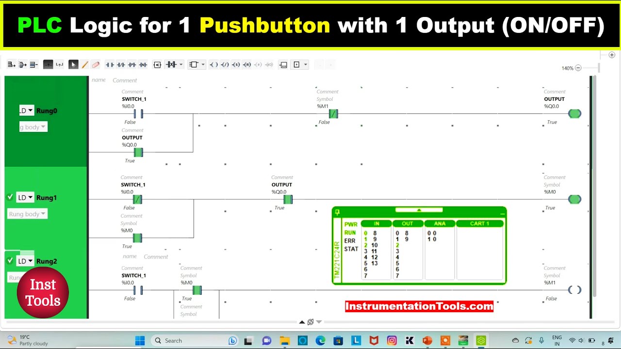
The PLC program for the given logic is shown below.
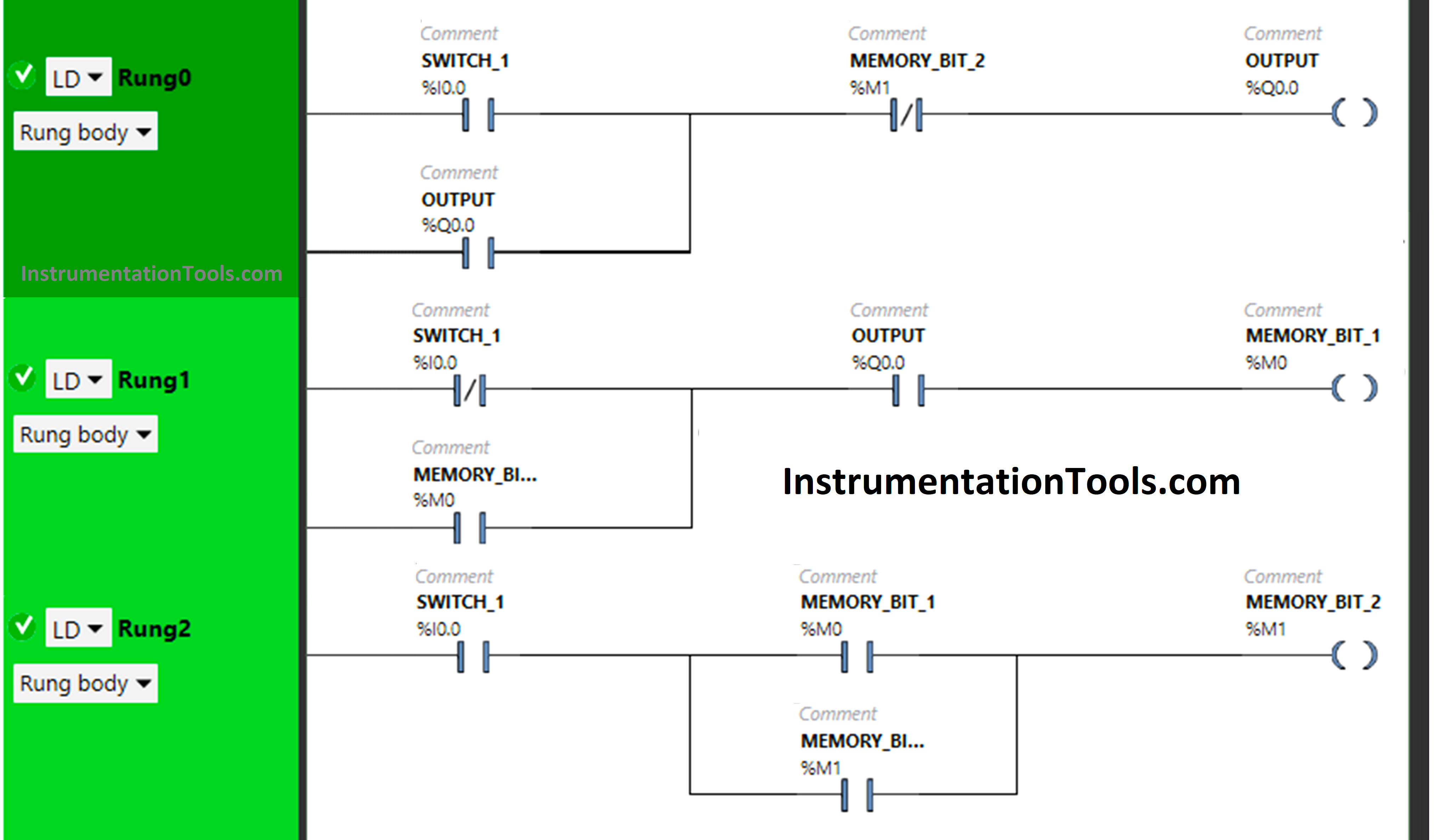
PLC 1 Push Button to Turn ON or OFF 1 Output

PLC Logic Description

In this logic, we used Schneider Electric PLC software.

In the above program, we have used Normally Open Contacts as well as Normally Closed Contacts and Memory Bits.

In Rung 0:

  1. Normally Open Contact is used for Push Button 1 to turn ON the output.
  2. Normally Closed Contact is used for Memory Bit 2 to turn OFF the output.
  3. Latching is used for Output so that when Push Button 1 is released, Output still remains ON.

In Rung 1:

  1. Normally Closed Contact is used for Push Button 1, and Normally Open Contact is used for Output to turn ON Memory Bit 1.
  2. As Memory Bit stores the data, Memory Bit 1 is used to store the data that Push Button 1 has released.

In Rung 2:

  1. Normally Open Contact is used for Push Button 1 to turn ON the Memory Bit 2.
  2. Memory Bit 1 is used to store the data that Push Button 1 is pressed again a second time.
  3. Memory Bit 2 i.e. latched with Memory Bit 1 is used to turn OFF the Output, So that when Memory Bit 2 turns ON in Rung 2, Normally Closed Contact used for Memory Bit 2 in Rung 0 will be in True state, and Output will turn OFF.

So, when Push Button 1 is pressed, the signal will flow through it as Normally Open Contact is used for Push Button 1 in Rung 0. In a false state, Normally Closed Contact used for Memory Bit 1 also passes the signal and Output will turn ON.

When Push Button 1 is released, Output will remain ON as Latching is used for Output in Rung 0. When Push Button 1 is released, Normally Closed Contact used for Push Button 1 in Rung 1 will be false state and allow the signal to pass.

Normally Open Contact Used for Output in Rung 1 will also pass the signal as it is in True state and Memory Bit 1 will turn ON which is connected with Push Button 1 and Output in Rung 1.

When Memory Bit 1 turns ON, it will store the data that Push Button 1 has been released. When Push Button 1 is pressed again, Memory Bit 1in Rung 2 will turn OFF and Memory Bit 2 will turn ON  and store the data that Push Button 1 is pressed again i.e. latched with Memory Bit 1 in Rung 2.

So, When Memory Bit 2 is turned ON in Rung 2, Normally Closed Contact used for Memory  Bit 2 in Rung 0 will be in True state and Output will turn OFF.

When Push Button 1 is released again, Output will remain OFF as Normally Open Contact used for  Push Button 1 in Rung 0 will be in a false state and does not allow the signal to pass the the Output.

PLC Simulation Results

The PLC program was simulated and results are shown below.

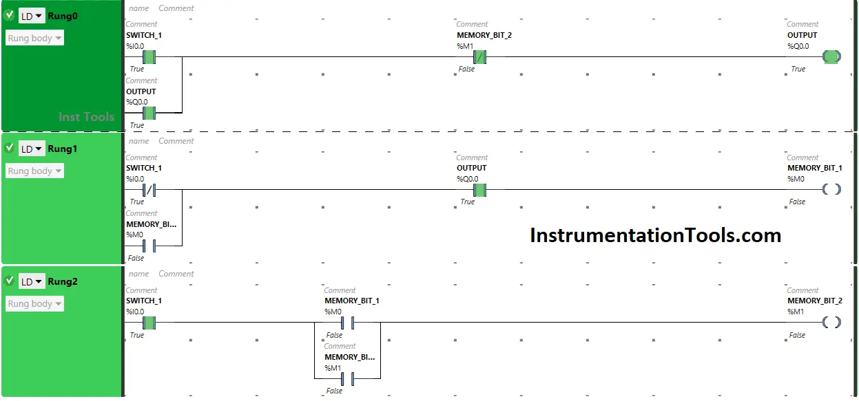
When Push Button 1 is PRESSED
PLC Push Button ON OFF

The signal flows through Push Button 1 as it is in true state and Output will turn ON.

In a false state, Memory Bit 2 in Rung 0 also passes the signal to turn ON the Output as Normally Closed Contact is used for Memory Bit 2 in Rung 0.

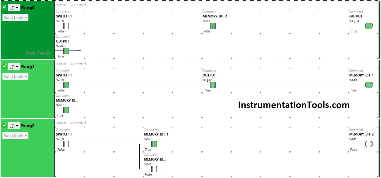
When Push Button 1 is RELEASED
Switching On and OFF by Single Push Button

When Push Button I is released, Output will remain ON as Latching is used for the Output in Rung 0.

In Rung 1, Memory Bit will turn ON as Normally Closed Contact used for Push Button 1 will be in a false state, and Normally Open Contact used for Output will be in a True state.

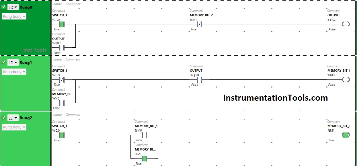
When Push Button 1 is PRESSED Again (Second Press)
Single Push Button On Off PLC Program

Pressing Push Button I again will turn OFF the Output because Memory Bit 2 in Rung 0 and Rung 2 will turn ON.

So, Normally Closed Contact used for Memory Bit 2 in Rung 0 will be in true state and does not allow the signal to pass to the Output.

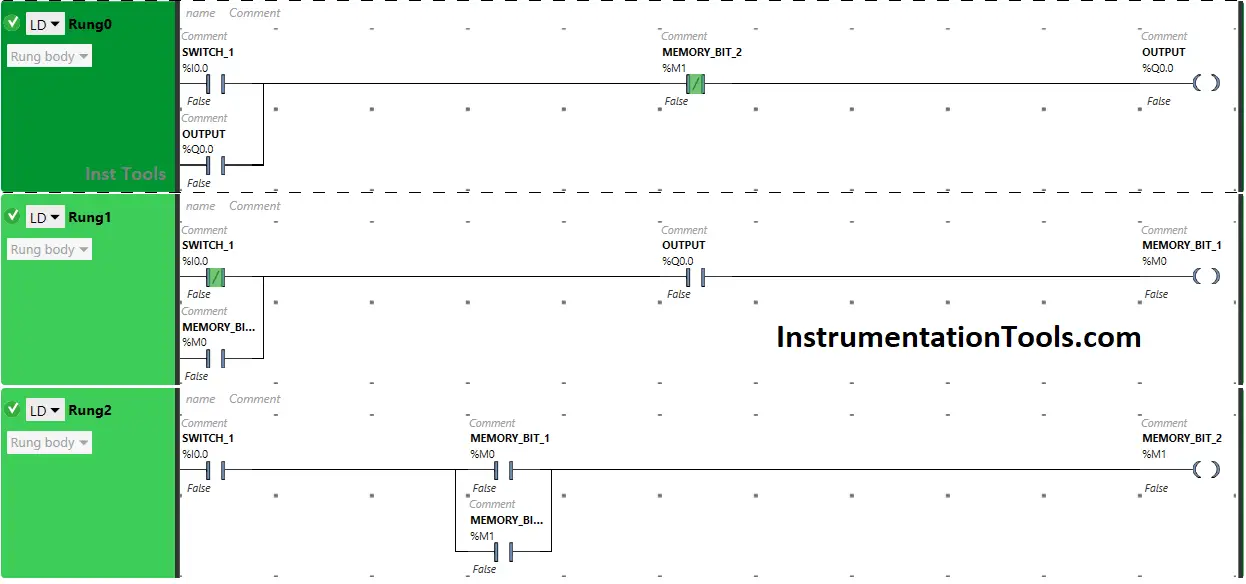
When Push Button 1 is RELEASED Again (Second Release)
Turn ON and OFF PLC Output with one Push button

When Push Button I is released again, Output will remain OFF as Normally Open Contact used for Push Button 1 in Rung 0  will be in a false state and will not pass signal to the output.

If you liked this article, please subscribe to our YouTube Channel for PLC and SCADA video tutorials.

You can also follow us on Facebook and Twitter to receive daily updates.

Read Next:

  • Push button Motor PLC Ladder Logic
  • Basic PLC Alarm Programming Example
  • Run 4 Motors Push button PLC Program
  • Start Stop of one Motor PLC program
  • PLC Automatic Control of Two Outputs
Don't Miss Our Updates
Be the first to get exclusive content straight to your email.
We promise not to spam you. You can unsubscribe at any time.
Invalid email address
You've successfully subscribed !

Continue Reading

What are Trends in SCADA?
PLC Timer Practice Exercise: Coffee Machine Programming
Extended Timer Logic in PLC
PLC Program for Positive Edge Pulse Output for One Scan Cycle
Demo of a SCADA Software – Level Control System
What is Process Control?
Share This Article
Facebook Whatsapp Whatsapp LinkedIn Copy Link
Share
Leave a Comment

Leave a Reply Cancel reply

Your email address will not be published. Required fields are marked *

Stay Connected

128.3kFollowersLike
69.1kFollowersFollow
210kSubscribersSubscribe
38kFollowersFollow

Categories

Explore More

Basic Pumping System Application Used in Industrial Automation
SCADA and HMI Systems – Differences, Similarities, Purpose
Top Free PLC Software
Elevator PLC Ladder Logic
PLC Structured Text Program for Light Sequences via Timers
Compare Online and Offline PLC Programs
What are High-Speed Inputs in PLC?
Types of Industrial Control Systems

Keep Learning

Repeat Until Statement in SCL Language

Repeat Until Statement in SCL Language

Creating Logic in Intouch Using Scripting

Create Logic with InTouch Scada using Scripting

AI AO DI DO Signals

What are AI, AO, DI, and DO? – Definition, Examples, Purpose

PLC or DCS Control System Spares

PLC or DCS Control System Spares

Node-RED in PLC Automation

Node-RED in PLC Industrial Automation

Siemens PLC Course for Beginners

Siemens PLC Course for Beginners: Problems and Solutions

Job Skills Required for Industrial Electrical Maintenance

Job Skills Required for Industrial Electrical Maintenance

PLC Interview Questions and Answers

PLC Interview Questions and Answers

Learn More

Power Electronics Objective Questions

Single Phase Voltage Source Inverter (VSI) Objective Questions

Time Response Analysis

Time Response of First Order Systems Objective Questions

PLC Program for Selective Execution of the Application

PLC Selective Execution of the Application – Example Program

User Defined Data Types - UDT

User Defined Data Types (UDT) – Purpose, Need, Tutorial

Inverse Transducers Objective Questions

Inverse Transducers Objective Questions

Sealed Bellows Temperature Sensors

Bellows Pressure Sensors Working Principle Animation

Pressure Safety Valves Functional Testing

Pressure Safety Valves Functional Testing

Digital Electronics Multiple Choice Questions

1’s, 2’s, 9’s & 10’s Complements Multiple Choice Questions

Menu

  • About
  • Privacy Policy
  • Copyright

Quick Links

  • Learn PLC
  • Helping Hand
  • Part Time Job

YouTube Subscribe

Follow US
All rights reserved. Reproduction in whole or in part without written permission is prohibited.
Welcome Back!

Sign in to your account

Username or Email Address
Password

Lost your password?