Already we discussed about the basics of permissive and interlock circuits in previous post, also discussed about the basic motor control logic using forward & reverse control.
The interlock contacts installed in the previous section’s motor control circuit work fine (as discussed in previous article), but the motor will run only as long as each pushbutton switch is held down.
If we wanted to keep the motor running even after the operator takes his or her hand off the control switch(es), we could change the circuit in a couple of different ways:
we could replace the pushbutton switches with toggle switches, or we could add some more relay logic to “latch” the control circuit with a single, momentary actuation of either switch.
Motor Control Circuits
Let’s see how the second approach is implemented, since it is commonly used in industry:
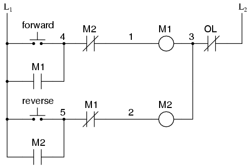
When the “Forward” pushbutton is actuated, M1 will energize, closing the normally-open auxiliary contact in parallel with that switch.
When the pushbutton is released, the closed M1 auxiliary contact will maintain current to the coil of M1, thus latching the “Forward” circuit in the “on” state.
The same sort of thing will happen when the “Reverse” pushbutton is pressed.
These parallel auxiliary contacts are sometimes referred to as seal-in contacts, the word “seal” meaning essentially the same thing as the word latch.
However, this creates a new problem: how to stop the motor! As the circuit exists right now, the motor will run either forward or backward once the corresponding pushbutton switch is pressed, and will continue to run as long as there is power.
To stop either circuit (forward or backward), we require some means for the operator to interrupt power to the motor contactors. We’ll call this new switch, Stop:
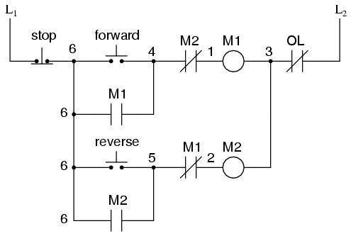
Now, if either forward or reverse circuits are latched, they may be “unlatched” by momentarily pressing the “Stop” pushbutton, which will open either forward or reverse circuit, de-energizing the energized contactor, and returning the seal-in contact to its normal (open) state.
The “Stop” switch, having normally-closed contacts, will conduct power to either forward or reverse circuits when released.
So far, so good. Let’s consider another practical aspect of our motor control scheme before we quit adding to it. If our hypothetical motor turned a mechanical load with a lot of momentum, such as a large air fan, the motor might continue to coast for a substantial amount of time after the stop button had been pressed.
This could be problematic if an operator were to try to reverse the motor direction without waiting for the fan to stop turning.
If the fan was still coasting forward and the “Reverse” pushbutton was pressed, the motor would struggle to overcome that inertia of the large fan as it tried to begin turning in reverse, drawing excessive current and potentially reducing the life of the motor, drive mechanisms, and fan. W
hat we might like to have is some kind of a time-delay function in this motor control system to prevent such a premature startup from happening.
Let’s begin by adding a couple of time-delay relay coils, one in parallel with each motor contactor coil.
If we use contacts that delay returning to their normal state, these relays will provide us a “memory” of which direction the motor was last powered to turn.
What we want each time-delay contact to do is to open the starting-switch leg of the opposite rotation circuit for several seconds, while the fan coasts to a halt.
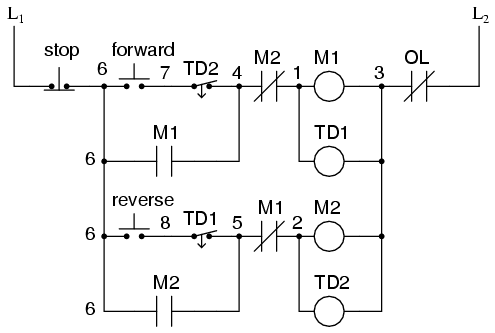
If the motor has been running in the forward direction, both M1 and TD1 will have been energized. This being the case, the normally-closed, timed-closed contact of TD1 between wires 8 and 5 will have immediately opened the moment TD1was energized.
When the stop button is pressed, contact TD1 waits for the specified amount of time before returning to its normally-closed state, thus holding the reverse pushbutton circuit open for the duration so M2 can’t be energized.
When TD1 times out, the contact will close and the circuit will allow M2 to be energized, if the reverse pushbutton is pressed. In like manner, TD2 will prevent the “Forward” pushbutton from energizing M1 until the prescribed time delay after M2(and TD2) have been de-energized.
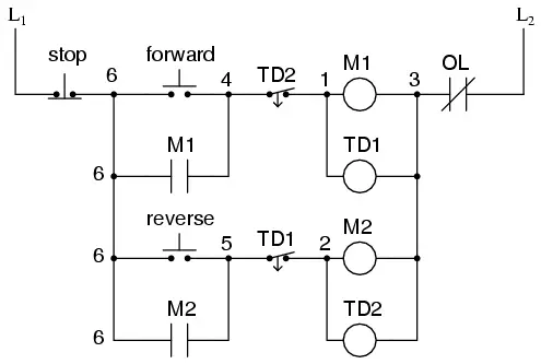
The careful observer will notice that the time-interlocking functions of TD1 and TD2 render the M1 and M2 interlocking contacts redundant.
We can get rid of auxiliary contacts M1 and M2 for interlocks and just use TD1 and TD2‘s contacts, since they immediately open when their respective relay coils are energized, thus “locking out” one contactor if the other is energized.
Each time delay relay will serve a dual purpose: preventing the other contactor from energizing while the motor is running, and preventing the same contactor from energizing until a prescribed time after motor shutdown.
The resulting circuit has the advantage of being simpler than the previous example:
Summary
- Motor contactor (or “starter”) coils are typically designated by the letter “M” in ladder logic diagrams.
- Continuous motor operation with a momentary “start” switch is possible if a normally-open “seal-in” contact from the contactor is connected in parallel with the start switch, so that once the contactor is energized it maintains power to itself and keeps itself “latched” on.
- Time delay relays are commonly used in large motor control circuits to prevent the motor from being started (or reversed) until a certain amount of time has elapsed from an event.
Credits : Roger Hollingsworth
If you liked this article, then please subscribe to our YouTube Channel for PLC and SCADA video tutorials.
You can also follow us on Facebook and Twitter to receive daily updates.
Read Next:
- DC Motor Speed
- Single Phase AC Induction Motors
- Induction Motor Torque Versus Slip
- Power Factor
- Impedance in RL Circuits
