A wise PLC programmer once told me that the first thing any aspiring programmer should learn about the PLC they intend to program is how the digital memory of that PLC is organized. This is sage advice for any programmer, especially on systems where memory is limited, and/or where I/O has a fixed association with certain locations in the system’s memory.
Virtually every microprocessor-based control system comes with a published memory map showing the organization of its limited memory: how much is available for certain functions, which addresses are linked to which I/O points, how different locations in memory are to be referenced by the programmer.
Discrete input and output channels on a PLC correspond to individual bits in the PLC’s memory array. Similarly, analog input and output channels on a PLC correspond to multi-bit words (contiguous blocks of bits) in the PLC’s memory.
The association between I/O points and memory locations is by no means standardized between different PLC manufacturers, or even between different PLC models designed by the same manufacturer. This makes it difficult to write a general tutorial on PLC addressing, and so my ultimate advice is to consult the engineering references for the PLC system you intend to program.
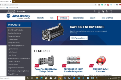
The most common brand of PLC in use is Allen-Bradley (Rockwell), which happens to use a unique form of I/O addressing (Note 1), students tend to find confusing. For these two reasons (popularity and confusion), I will focus on Allen-Bradley addressing conventions for the bulk of this section.
Note 1 : The most modern Allen-Bradley PLCs have all but done away with fixed-location I/O addressing, opting instead for tag name based I/O addressing. However, enough legacy Allen-Bradley PLC systems still exist in industry to warrant coverage of these addressing conventions.
PLC Memory Map
The following table shows a partial memory map for an Allen-Bradley SLC 500 PLC

Memory Map also called the data table, this map shows the addressing of memory areas reserved for programs entered by the user. Other areas of memory exist within the SLC 500 processor, but these other areas are inaccessible to the technician writing PLC programs.
Note that Allen-Bradley’s use of the word “file” differs from personal computer parlance. In the SLC 500 controller, a “file” is a block of random-access memory used to store a particular type of data.
By contrast, a “file” in a personal computer is a contiguous collection of data bits with collective meaning (e.g. a word processing file or a spreadsheet file), usually stored on the computer’s hard disk drive.
Within each of the Allen-Bradley PLC’s “files” are multiple “elements,” each element consisting of a set of bits (8, 16, 24, or 32) representing data.
Elements are addressed by number following the colon after the file designator, and individual bits within each element addressed by a number following a slash mark. For example, the first bit (bit 0) of the second element in file 3 (Binary) would be addressed as B3:2/0.
In Allen-Bradley PLCs such as the SLC 500 and PLC-5 models, files 0, 1, and 2 are exclusively reserved for discrete outputs, discrete inputs, and status bits, respectively.
Thus, the letter designators O, I, and S (file types) are redundant to the numbers 0, 1, and 2 (file numbers).
Other file types such as B (binary), T (timers), C (counters), and others have their own default file numbers (3, 4, and 5, respectively), but may also be used in some of the user-defined file numbers (10 and above).
For example, file 7 in an Allen-Bradley controller is reserved for data of the “integer” type (N), but integer data may also be stored in any file numbered 10 or greater at the user’s discretion.
Thus, file numbers and file type letters for data types other than output (O), input (I), and status (S) always appear together.
You would not typically see an integer word addressed as N:30 (integer word 30 in the PLC’s memory) for example, but rather as N7:30 (integer word 30 in file 7 of the PLC’s memory) to distinguish it from other integer word 30’s that may exist in other files of the PLC’s memory.
This file-based addressing notation bears further explanation. When an address appears in a PLC program, special characters are used to separate (or “delimit”) different fields from each other.
The general scheme for Allen-Bradley SLC 500 PLCs is shown here:

Not all file types need to distinguish individual words and bits. Integer files (N), for example, consist of one 16-bit word for each element. For instance, N7:5 would be the 16-bit integer word number five held in file seven.
A discrete input file type (I), though, needs to be addressed as individual bits because each separate I/O point refers to a single bit. Thus, I:3/7 would be bit number seven residing in input element three.
The “slash” symbol is necessary when addressing discrete I/O bits because we do not wish to refer to all sixteen bits in a word when we just mean a single input or output point on the PLC.
Integer numbers, by contrast, are collections of 16 bits each in the SLC 500 memory map, and so are usually addressed as entire words rather than bit-by-bit .
Certain file types such as timers are more complex. Each timer “element ” consists of two different 16-bit words (one for the timer’s accumulated value, the other for the timer’s target value) in addition to no less than three bits declaring the status of the timer (an “Enabled” bit, a “Timing” bit, and a “Done” bit).
Thus, we must make use of both the decimal-point and slash separator symbols when referring to data within a timer. Suppose we declared a timer in our PLC program with the address T4:2, which would be timer number two contained in timer file four.
If we wished to address that timer’s current value, we would do so as T4:2.ACC (the “Accumulator” word of timer number two in file four). The “Done” bit of that same timer would be addressed as T4:2/DN (the “Done” bit of timer number two in file four)
A hallmark of the SLC 500’s addressing scheme common to many legacy PLC systems is that the address labels for input and output bits explicitly reference the physical locations of the I/O channels.
For instance, if an 8-channel discrete input card were plugged into slot 4 of an Allen Bradley SLC 500 PLC, and you wished to specify the second bit (bit 1 out of a 0 to 7 range), you would address it with the following label: I:4/1.
Addressing the seventh bit (bit number 6) on a discrete output card plugged into slot 3 would require the label O:3/6. In either case, the numerical structure of that label tells you exactly where the real-world input signal connects to the PLC.
PLC Memory Mapping Example
To illustrate the relationship between physical I/O and bits in the PLC’s memory, consider this example of an Allen-Bradley SLC 500 PLC, showing one of its discrete input channels energized (the switch being used as a “Start” switch for an electric motor):

If an input or output card possesses more than 16 bits – as in the case of the 32-bit discrete output card shown in slot 3 of the example SLC 500 rack – the addressing scheme further subdivides each element into words and bits (each “word” being 16 bits in length).
Thus, the address for bit number 27 of a 32-bit input module plugged into slot 3 would be I:3.1/11 (since bit 27 is equivalent to bit 11 of word 1 – word 0 addressing bits 0 through 15 and word 1 addressing bits 16 through 31):

A close-up photograph of a 32-bit DC input card for an Allen-Bradley SLC 500 PLC system shows this multi-word addressing:

The first sixteen input points on this card (the left-hand LED group numbered 0 through 15) are addressed I:X.0/0 through I:X.0/15, with “X” referring to the slot number the card is plugged into. The next sixteen input points (the right-hand LED group numbered 16 through 31) are addressed I:X.1/0 through I:X.1/15.
Legacy PLC systems typically reference each one of the I/O channels by labels such as “I:1/3” (or equivalent ) indicating the actual location of the input channel terminal on the PLC unit.
The IEC 61131-3 programming standard refers to this channel-based addressing of I/O data points as direct addressing. A synonym for direct addressing is absolute addressing.
Addressing I/O bits directly by their card, slot, and/or terminal labels may seem simple and elegant, but it becomes very cumbersome for large PLC systems and complex programs.
Every time a technician or programmer views the program, they must “translate” each of these I/O labels to some real-world device (e.g. “Input I:1/3 is actually the Start push-button for the middle tank mixer motor”) in order to understand the function of that bit.
A later effort to enhance the clarity of PLC programming was the concept of addressing variables in a PLC’s memory by arbitrary names rather than fixed codes.
The IEC 61131-3 programming standard refers to this as symbolic addressing in contrast to “direct” (channel-based) addressing, allowing programmers arbitrarily name I/O channels in ways that are meaningful to the system as a whole.
To use our simple motor “Start” switch example, it is now possible for the programmer to designate input I:1/3 (an example of a direct address) as “Motor start switch” (an example of a symbolic address) within the program, thus greatly enhancing the readability of the PLC program.
Initial implementations of this concept maintained direct addresses for I/O data points, with symbolic names appearing as supplements to the absolute addresses.
The modern trend in PLC addressing is to avoid the use of direct addresses such as I:1/3 altogether, so they do not appear anywhere in the programming code.
The Allen-Bradley “Logix” series of programmable logic controllers is the most prominent example of this new convention at the time of this writing.
Each I/O point, regardless of type or physical location, is assigned a tag name which is meaningful in a real-world sense, and these tag names (or symbols as they are alternatively called) are referenced to absolute I/O channel locations by a database file.
An important requirement of tag names is that they contain no space characters between words (e.g. instead of “Motor start switch”, a tag name should use hyphens or underscore marks as spacing characters: “Motor start switch”), since spaces are generally assumed by computer programming languages to be delimiters (separators between different variables).
Having introduced Allen-Bradley’s addressing notation for SLC 500 model PLCs, I will now abandon it in favor of the modern convention of symbolic addressing throughout the rest of the articles, so as to avoid making the programming examples brand- or model-specific. Each data point within my PLC programs will bear its own tag name rather than a direct (channel-based) address label.
Credits : by Tony R. Kuphaldt – Creative Commons Attribution 4.0 License
PLC Tutorials :
What is Programmable Logic Controller ?
What is Ladder Diagram Programming ?
History of Programmable Logic Controllers
Mis-conceptions of PLC Ladder Logic
Contacts and coils in PLC
Digital Input and Output Modules
Analog I/O and Network I/O
PLC Input/Output Modules
Memory Mapping in PLC
Analog Input Scaling
PLC Example with Switches
Counter Instructions
Timer Instructions
Math instructions
Data Instructions
Ladder Logic Questions
If you liked this article, then please subscribe to our YouTube Channel for PLC and SCADA video tutorials.
You can also follow us on Facebook and Twitter to receive daily updates.