To study the working of Converter (BCD TO INT/ INT TO BCD) in Allen Bradley programmable logic controllers (plc).
Integer to BCD Converter Block Diagram
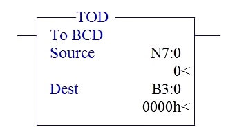
Block Name : TOD (Integer to BCD Converter )
In the above picture, there are totally two parameter,
SOURCE – Integer Value address
DESTINATION – BCD Value address
BCD to Integer Converter Block Diagram
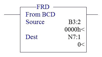
Block Name: FRD (BCD to Integer Converter )
In the above picture, there are totally two parameter,
SOURCE – BCD Value address
DESTINATION – Integer Value address
INTEGER TO BCD CONVERTER
In Allen Bradley RS500 Ladder logic, Integer to BCD converter block is called as TOD.
It will convert the integer to respective BCD Value
Ex:
Integer-1020
BCD– 0001-0000-0010-0000
Example PLC Program:
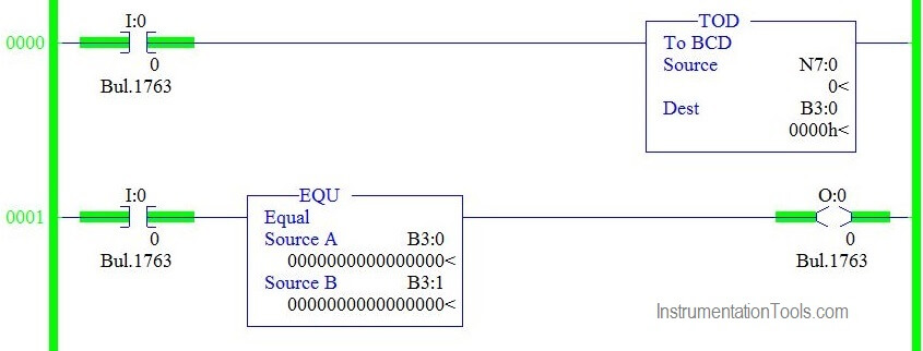
Rung 0000 :
I:0/0 giving input condition to BCD converter. When it goes ON, value placed in N7:0 is converter into BCD and store the value in B3:0.
Rung 0001 :
Equal comparator block is used to give output to O:0/0 when B3:0 equals B3:1.O:0/0 is enabled because B3:0 and B3:1 are 0.
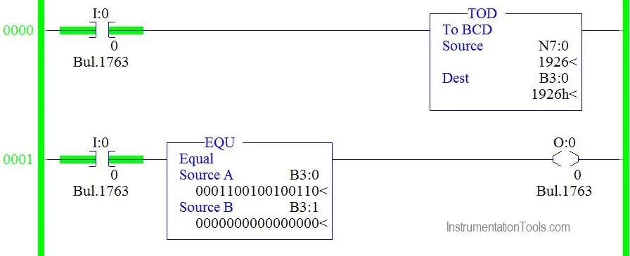
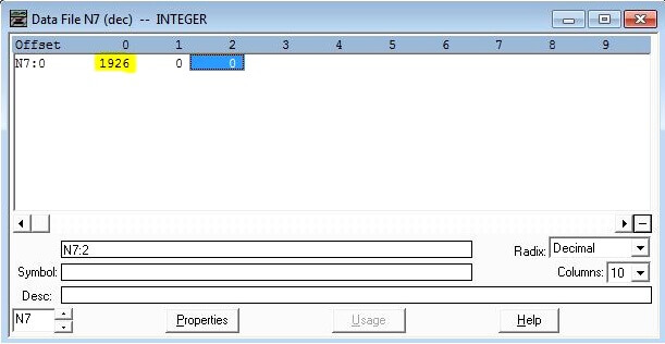
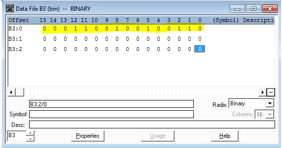
Rung 0000 :
I:0/0 giving input condition to BCD converter. When it goes ON, value placed in N7:0-1926 is converter into BCD (0001100100100110) and store the value in B3:0.
Rung 0001 :
Equal comparator block is used to give output to O:0/0 when B3:0 equals B3:1.
O:0/0 is turned off because B3:0 and B3:1 are not equal..
BCD TO INTEGER CONVERTER
In Allen Bradley RS500 Ladder logic, BCD to Integer converter block is called as FRD.
It will convert the BCD to respective Integer Value
Ex:
BCD– 1001-1001-1001-1001
Integer-9999
Example PLC Program:
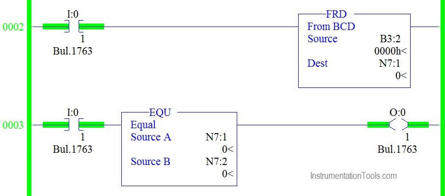
Rung 0000 :
I:0/1 giving input condition to INT converter. When it goes ON, value placed in B3:2 is converter into INT and store the value in N7:1.
Rung 0001 :
Equal comparator block is used to give output to O:0/1 when N7:1 equals N7:2.
O:0/1 is enabled because N7:1 and N7:2 are 0.
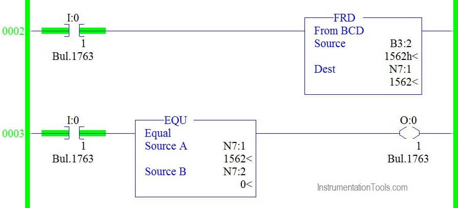
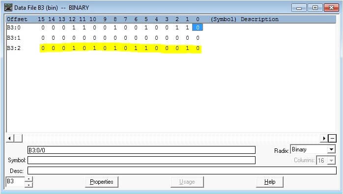
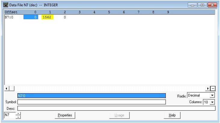
Rung 0000 :
I:0/0 giving input condition to INT converter. When it goes ON, value placed in B3:2-0001010001010010 is converter into INT -1562 and store the value in N7:1.
Rung 0001 :
Equal comparator block is used to give output to O:0/1 when N7:2 equals N7:1.
O:0/1 is turned off because N7:1 and N7:2 are not equal..
Conclusion:
We can use this explanation to understand the working of Converters in Allen Bradley programmable logic controllers (plc).
If you liked this article, then please subscribe to our YouTube Channel for PLC and SCADA video tutorials.
You can also follow us on Facebook and Twitter to receive daily updates.
Read Next:

