Inst ToolsInst ToolsInst Tools
  • Courses
  • Automation
    • PLC
    • Control System
    • Safety System
    • Communication
    • Fire & Gas System
  • Instrumentation
    • Design
    • Pressure
    • Temperature
    • Flow
    • Level
    • Vibration
    • Analyzer
    • Control Valve
    • Switch
    • Calibration
    • Erection & Commissioning
  • Interview
    • Instrumentation
    • Electrical
    • Electronics
    • Practical
  • Q&A
    • Instrumentation
    • Control System
    • Electrical
    • Electronics
    • Analog Electronics
    • Digital Electronics
    • Power Electronics
    • Microprocessor
  • Request
Search
  • Books
  • Software
  • Projects
  • Process
  • Tools
  • Basics
  • Formula
  • Power Plant
  • Root Cause Analysis
  • Electrical Basics
  • Animation
  • Standards
  • 4-20 mA Course
  • Siemens PLC Course
Reading: Purpose of Loop Diagrams
Share
Font ResizerAa
Inst ToolsInst Tools
Font ResizerAa
  • Courses
  • Design
  • PLC
  • Interview
  • Control System
Search
  • Courses
  • Automation
    • PLC
    • Control System
    • Safety System
    • Communication
    • Fire & Gas System
  • Instrumentation
    • Design
    • Pressure
    • Temperature
    • Flow
    • Level
    • Vibration
    • Analyzer
    • Control Valve
    • Switch
    • Calibration
    • Erection & Commissioning
  • Interview
    • Instrumentation
    • Electrical
    • Electronics
    • Practical
  • Q&A
    • Instrumentation
    • Control System
    • Electrical
    • Electronics
    • Analog Electronics
    • Digital Electronics
    • Power Electronics
    • Microprocessor
  • Request
Follow US
All rights reserved. Reproduction in whole or in part without written permission is prohibited.
Inst Tools > Blog > Instrumentation Design > Purpose of Loop Diagrams

Purpose of Loop Diagrams

Loop diagrams are very important Instrumentation design deliverables. Their purpose is to represent components of a instrument loop.

Last updated: September 30, 2021 2:39 am
Editorial Staff
Instrumentation Design
1 Comment
Share
4 Min Read
SHARE

Loop diagrams are very important Instrumentation design deliverable. Mainly for construction contractor who will install and wire all the loops. It helps them to track each and every tag correctly and easily while keeping log of the activities.

Contents
Loop DiagramDecoding the Information

Loop drawing are mostly drawn on drafting software like AutoCad but nowadays they can be generated automatically by intelligent design data base softwares.

Purpose of this particular Instrumentation design deliverable is but not limited to :

1) Showing how the control system is getting Instruments data and how it controlling output device. The complete wiring of the loop is shown for particular tag whether that tag is open loop or close loop.

2) Indicating the accessories associated with that loop for example some loops will have loop power indicator or some instruments will have extra displays.

3) Specifying all the point to point connection with cable details and their termination locations.

Loop Diagram

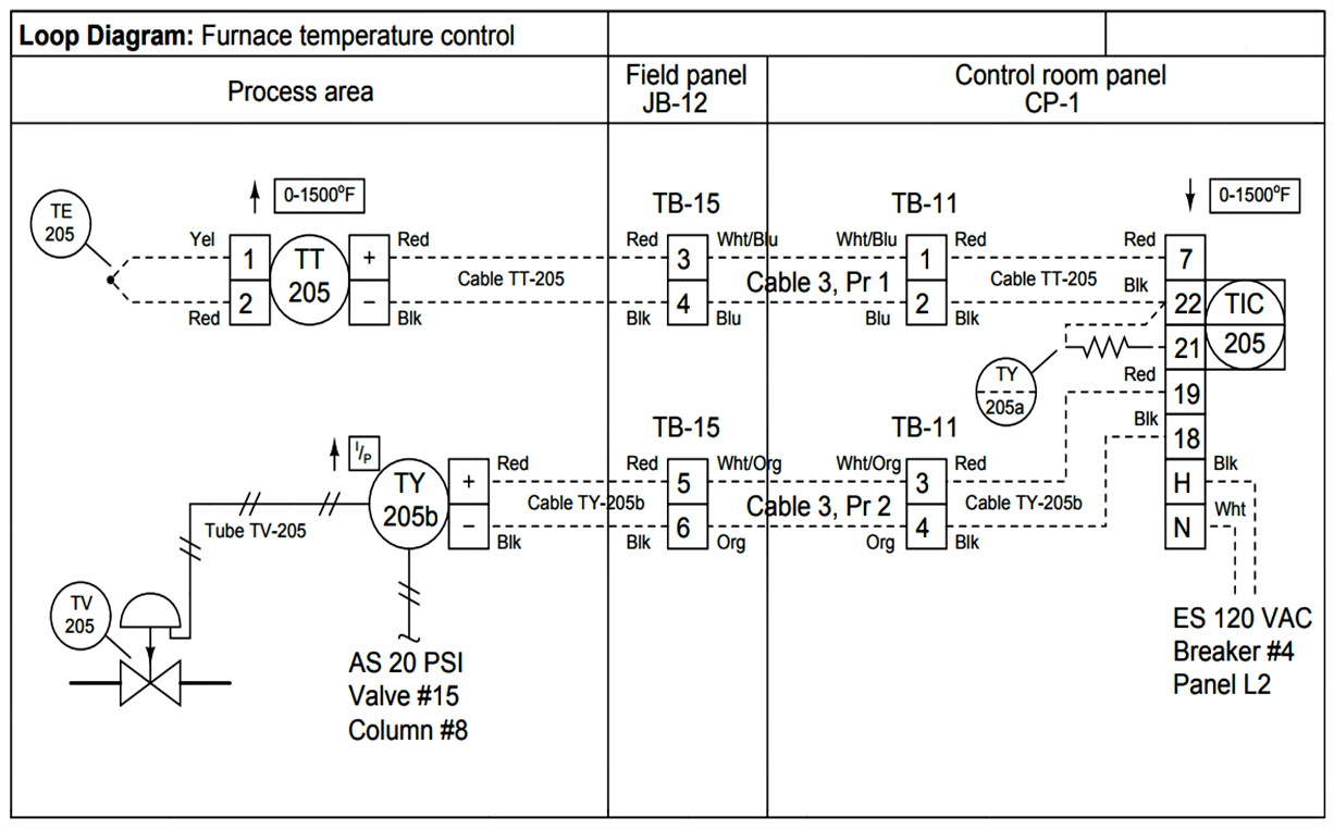
In below picture a sample loop drawing is shown

Purpose of Instrument Loop Diagrams

Decoding the Information

ISA 5.4 clearly states minimum and optional information that should be in Loop Diagram but let’s try to understand that using above loop diagram as an example.

At first glance we can see that whole diagram is divided into 3 main location wise parts viz Process area, Field Panel junction box and control room.

This is general format but due to complexity of the loops every case is different for example if remote I/Os are used format would be different but remember we have to show whole routing of the cable from the instrument to the very last terminal of the control panel.

Also note just like P&ID here we also indicate if it is electrical line or pneumatic via standard method.

In above loop diagram temperature element wiring to its transmitter is also shown with transmitter’s terminal numbers and colours of the cables.

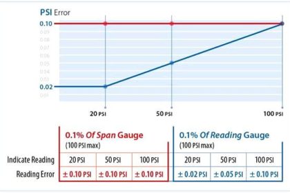
But Instrument range is also indicated above the transmitter, which is not compulsory or something should be mentioned in each loop diagram. Every loop diagram’s format would be different in some capacity.

Fundamental details like terminal numbers, cable tags, cable colours, location of each and every termination are main features of this deliverable. In above example we can clearly see termination are clearly mentioned with numbers also colour and tags of the cables are clearly indicated.

One very important factor is how that Instrument is powered up; here we can see it is loop powered instrument so no need to show additional power wiring but some instruments require separate power sources. In such cases power wiring indication is important, remember our aim is to explain the whole geography and architecture of the loop.

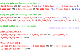
If there are any interlocks are acting on this loop that also needs to be shown properly and interlock description should also be added to notes if applicable.

Also for actuators it is very important to show fail safe position as per ISA-5.1(Instrumentation Symbols and Identification).

There are optional information that can be represented in loop drawing as and when needed like model and manufacturer details of equipments, reference to other deliverable and cross reference between loops where they use one device such as recorder.

Reference

  • ISA 5.4 – INSTRUMENT LOOP DIAGRAM

Author: Kalpit Patel

Read Next

  • Loop Diagram Question
  • Intrinsic Safe Calculation
  • Engineering Logic Diagrams
  • Electrical Schematics
  • Junction Box Schedule
Don't Miss Our Updates
Be the first to get exclusive content straight to your email.
We promise not to spam you. You can unsubscribe at any time.
Invalid email address
You've successfully subscribed !

Continue Reading

Instrumentation and Electrical Teams Interactions (Detail Design Engineering)
Tagging Philosophy for Junction Box, Cable, and Cable Drum
Design Basis for Fire Detection and Alarm System
Difference between Intrinsic Safe and Non-Intrinsic Safe Cables
Diaphragm Seal Material Selection
Instrumentation Engineer Activities & Documents – Detail Design Phase
Share This Article
Facebook Whatsapp Whatsapp LinkedIn Copy Link
Share
1 Comment
  • Raouf Ben Ghozlane says:
    December 2, 2020 at 5:55 pm

    A loop diagram for an instrumentation technician or engineer is very useful and important as a maintenance tool. It can be used to follow the connection line of an instrument in the field, hence easily locate the error or the malfunction.

    You will know through which cabinet and JBs the instrument is connected prior to enter the PLC or the DCS marshalling panel. Without the loop diagram it will be very difficult to have complete knowledge about the complete connection drawing.

    Reply

Leave a Reply Cancel reply

Your email address will not be published. Required fields are marked *

Stay Connected

128.3kFollowersLike
69.1kFollowersFollow
210kSubscribersSubscribe
38kFollowersFollow

Categories

Explore More

All About Turbine Meters
Pressure Control Valves vs Pressure Regulators
Troubleshooting a Power Supply Circuit
Major issues for Sensors Selection
Role of an Instrumentation Design Engineer for Beginners
Process Control Systems Philosophy Concept
Field Instruments Scaling and Unit Conversions
Technical Specification for Uninterrupted Power Supply (UPS) System

Keep Learning

Instrument Loop Diagram

How-to Create Instrument Loop Diagram (ILD)?

Control Valve Packing

Control Valve Packing

Heat Tracing Problems

Heat Tracing Problems

Motor Controls

Design and Implement Motor Control – Electrical Engineering

Instrument Air Compressor Control Philosophy

Instrument Air Compressor Control Philosophy

Water Vapor in Instrument Air Lines

How to Minimize Water Vapor in Instrument Air Lines?

Turbine-Compressor System Architecture

Turbine-Compressor System Architecture

Location of Measurement Displays

Location of Measurement Displays

Learn More

Thermovcouple Circuit

Thermocouple and its Principle

Mass Spectrometer Questions and Answers

Magnetic Deflection Mass Spectrometer Questions & Answers

What is an Oil Separator in HVAC?

What is an Oil Separator in HVAC?

Instrument Calibration Record

How to Create Calibration Records?

PLC Program using Counters

PLC Counters Program

Offline UPS

UPS Working Principle and Types – Offline and Online UPS Systems

Chromatography Questions & Answers

Detection System of Liquid Chromatography Questions & Answers

Level Measurement Multiple Choice Questions

Level Measurement Multiple Choice Questions

Menu

  • About
  • Privacy Policy
  • Copyright

Quick Links

  • Learn PLC
  • Helping Hand
  • Part Time Job

YouTube Subscribe

Follow US
All rights reserved. Reproduction in whole or in part without written permission is prohibited.
Welcome Back!

Sign in to your account

Username or Email Address
Password

Lost your password?