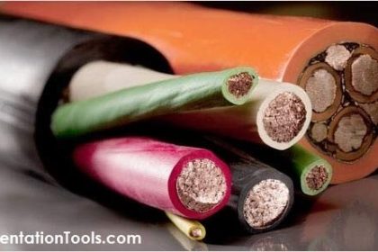
Difference between IS and Non-IS cables
- The IS and Non-IS cables are similar in construction like 1 pair, 2 pair or multi-pair cables with shield, insulation, armor etc.
- The entity parameter of the cables needs to be verified in IS calculations and if these values fulfill the requirements then they can be used in IS loops.
- The entity parameters of cables needs to be checked prior to ordering or selection of cables, specially for use in Gas Group IIC.
- The IS cable outer sheath insulation color is BLUE (most of cases) to identify in the plant which cables are IS cables while non IS cable outer sheath color is either Black or Grey.
- The terminals used in JB and in control cabinets is Blue color for IS circuit where as for Non IS it is generally Grey color.
- Generally IS and Non IS cables are segregated in cable trays/ duct while laying in the field (depending on project specifications).
IS (Intrinsic Safe) Loop calculation
Fundamentally the purpose of the IS circuits is to limit the energy going into the field so as to minimize the risk of ignition in hazardous atmosphere
Typical IS circuit
Refer figure below –
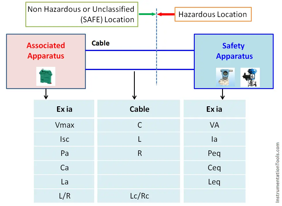
The safety apparatus is the field instruments (transmitters, valves, switches) which are installed in Hazardous area, they are intrinsically safe and Exi certified.
The associated apparatus (Barriers, Isolators) are installed in Non Hazardous area mainly in Control cabinets inside Instrument Rack Rooms or in control rooms. They are designed to limit the energy (voltage and current) available to safety apparatus. They are also Exi certified suitable to use with safety apparatus.
When devices are approved as Intrinsically safe, under the entity concept they have entity parameters listed in table below the figure.
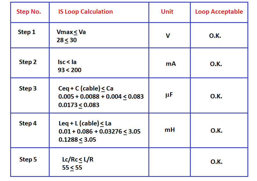
Following conditions should be met, for an IS circuit / loop
Condition 1
Vmax < Va
Isc < Ia
Pa < Peq
If there is a fault condition, the excess voltage or current from associated apparatus (non Hazardous area) could be transferred to the safety apparatus (intrinsically safe apparatus – field device). If the voltage or current (Va , Ia) exceeds the safety apparatus’ Vmax or Isc, the device can heat up or spark and ignite the gases in the hazardous area.
Condition 2
Ceq + C (cable) < Ca
Leq + L (cable) < La
C (cable) = Ca – Ceq
L (cable) = La – Leq
The Ca and La values describe the device‘s ability to store energy in the form of internal capacitance and internal inductance. This represents the maximum capacitance that may be connected to the specified terminals without invalidating safety.
Condition 3
Lc/Rc < L/R
The Lc/Rc ratio of the cable can be used as an alternative to the maximum value of L/R allowed by the associated apparatus. If this value is lower than that of the associated apparatus then the inductive effect of the cable can be ignored and the cable distance can be equivalent to the capacitance value.
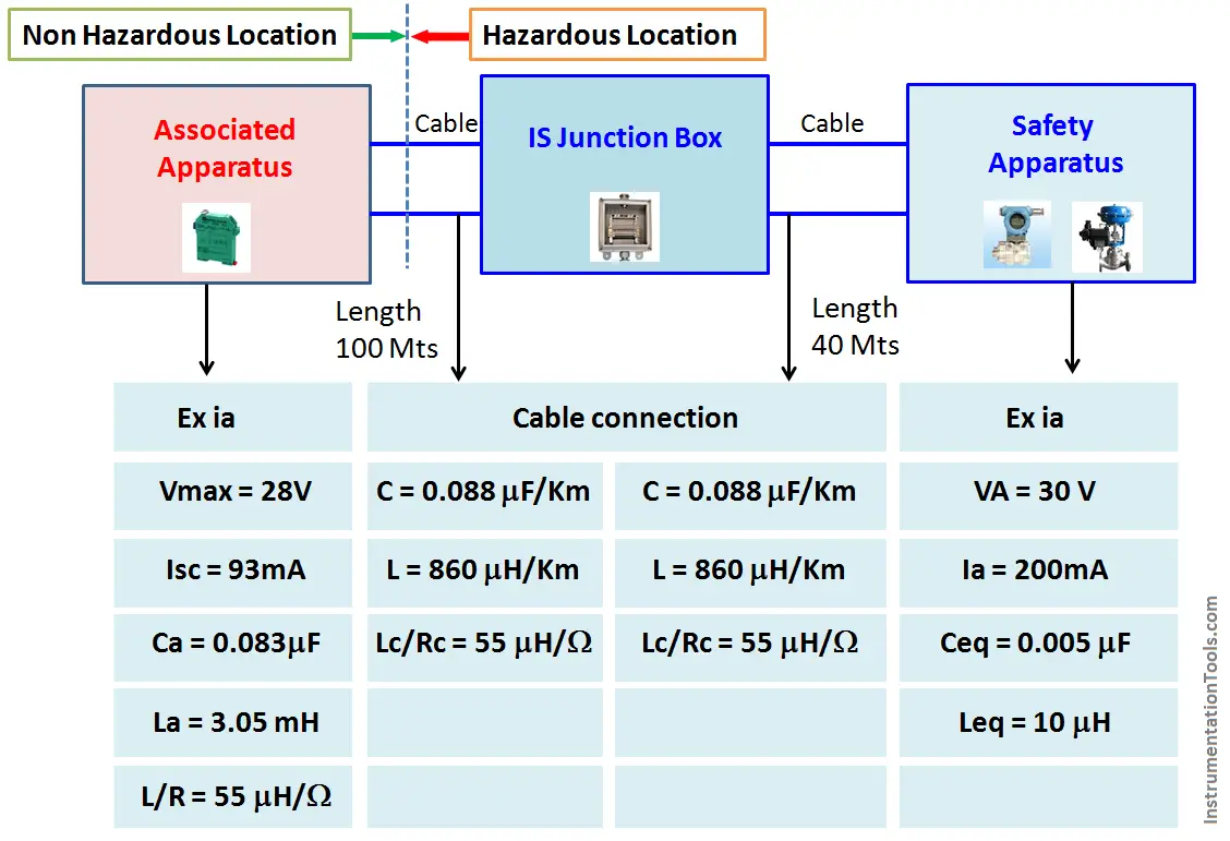
Example
Typical Non IS circuits
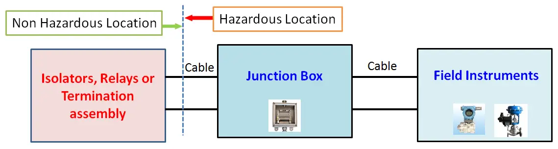
The diagram above shows a typical non IS circuit.
The cables used in this circuit does not need to have entity parameters.
This circuit is used in mainly non Hazardous areas or Non IS instruments and apparatus or Instruments with Exd approval.


What is the abbreviation of
Isc, Pa, Ca, La, L/R, Lc/Rc, VA, Ia, Peq, Ceq, Leq
Please confirm me the abbreviation.
Thank you for your good information.
There is a misconception that the Co values are defined by the design of barrier/isolator. The Co value is actually defined in IEC 60079-11: Table A.2. So any barrier/isolator with a 28 V safety description will have Co = 83 nF (Zone 0/1, IIC)
When Barrier is used in an ‘ic’ circuit then the permitted output parameters may be derived using a unity safety factor e.g. If the loop were Ex ic, the Co=272 nF (Zone 2; IIC), unity safety factor is defined in IEC 60079-11 for Ex ic.
Further, according to the Gas group IIB/ IIA, capacitance (Co) value can be considered as per Table A.2
-> the values of Lo and Co determined by the ignition curves and table given in Annex A shall be reduced to 50 % if both of the following conditions are met;
a) the total Li (Transmitter side) of the external circuit (excluding the cable) ≥ 1 % of the Lo (Barrier) value and
b) the total Ci (Transmitter side) of the external circuit (excluding the cable) ≥ 1 % of the Co (Barrier) value.
If BOTH parameters are greater than 1% of the output parameters then Co and Lo of the system should be reduced by a factor of two.
W.r.t above points parameters for IS cable shall be considered and IS calculation to be performed.
How to calculate LC/RC in above mentioned example??
Very informative!