Tagging of the junction box, cables, and cable drums is very important during front-end engineering design for the preparation of the JB schedule, cable schedule, cable drum schedule, etc.
In this article, we are going to discuss the tagging philosophy for junction boxes, cables, and cable drums.
Junction Box Tagging
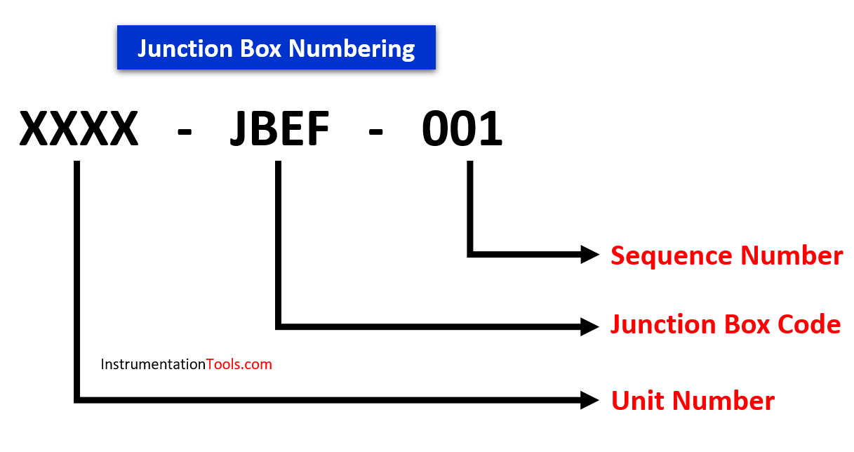
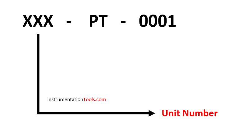
The given above is the basic structure of junction Box tagging philosophy
It includes,
- Unit Number
- Junction Box Code
- Sequence Number
Unit Number
Refer to the below article for details regarding the unit number
Junction Box Code
Each junction box is associated with an instrumented facility comprising of a series of letters depicting that junction box details based on the type of signals.
Below table indicates some of the junction box types
| LETTER | TYPE OF SIGNAL |
| JBA | Alarm (BPCS) |
| JBE | Analogue (BPCS) |
| JBS | Control – Solenoid Outputs (BPCS) |
| JBFF | Fieldbus Foundation (BPCS) |
| JBAX | Alarm (SIS) |
| JBEX | Analogue (SIS) |
| JBSX | Control – Solenoid Outputs (SIS) |
| JBAF | Alarm (F&G) |
| JBEF | Analogue (F&G) |
| JBPF | Power (F&G) |
Also Read: Instrumentation Project Documents
Junction Box Schedule
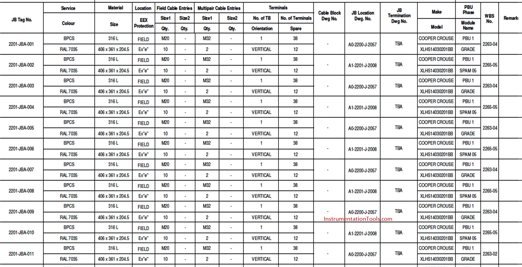
Reference drawings required for the preparation of the JB Schedule are
- Specifications for instrument junction boxes
- Specifications for cable glands
- Instrument cable schedule
- Junction box tagging philosophy
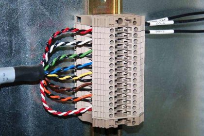
Cable Tagging
The below discussed the different ways where we used the cable tagging.
Field Instrument to Junction Box
Individual cables running between field instruments and junction boxes are normally identified by the instrument tag number itself.
Example:
Junction Box to Control Room
The below image shows the basic structure of cable tagging for cables from the junction box to the control room.
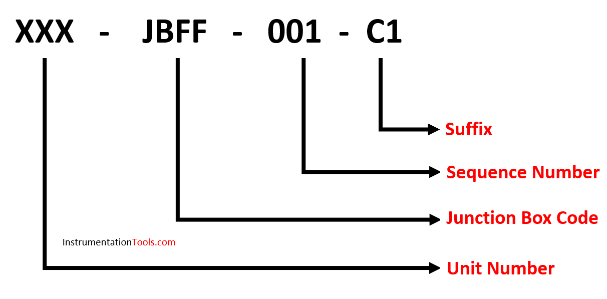
It includes,
- Unit Number
- Junction Box Code
- Sequence Number of Cable
- Cable Suffix
Cable Schedule
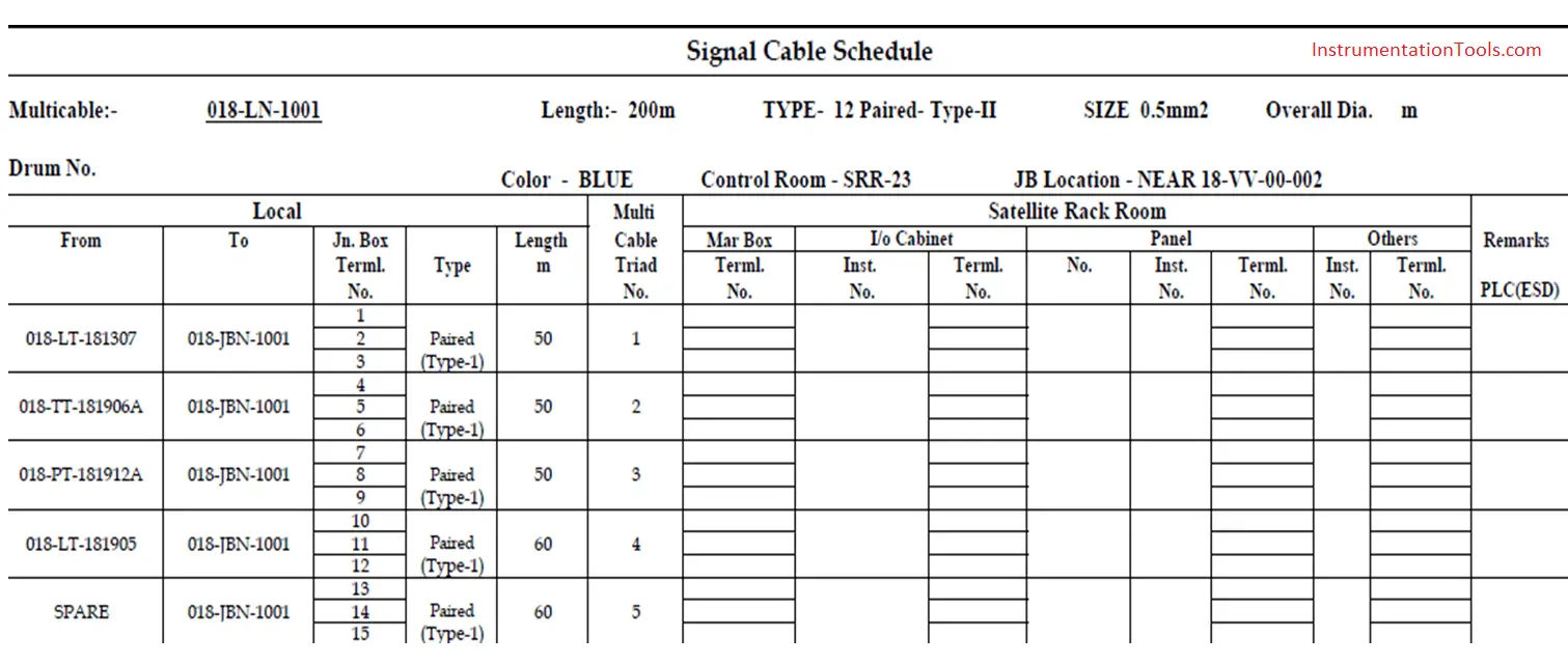
Reference drawings required for the preparation of the cable schedule are
- Instrumentation Index
- Cable Tagging Philosophy
- Cable and Junction Box Specification
- Instrumentation Design Basis
Instrument Cable Drum Tagging
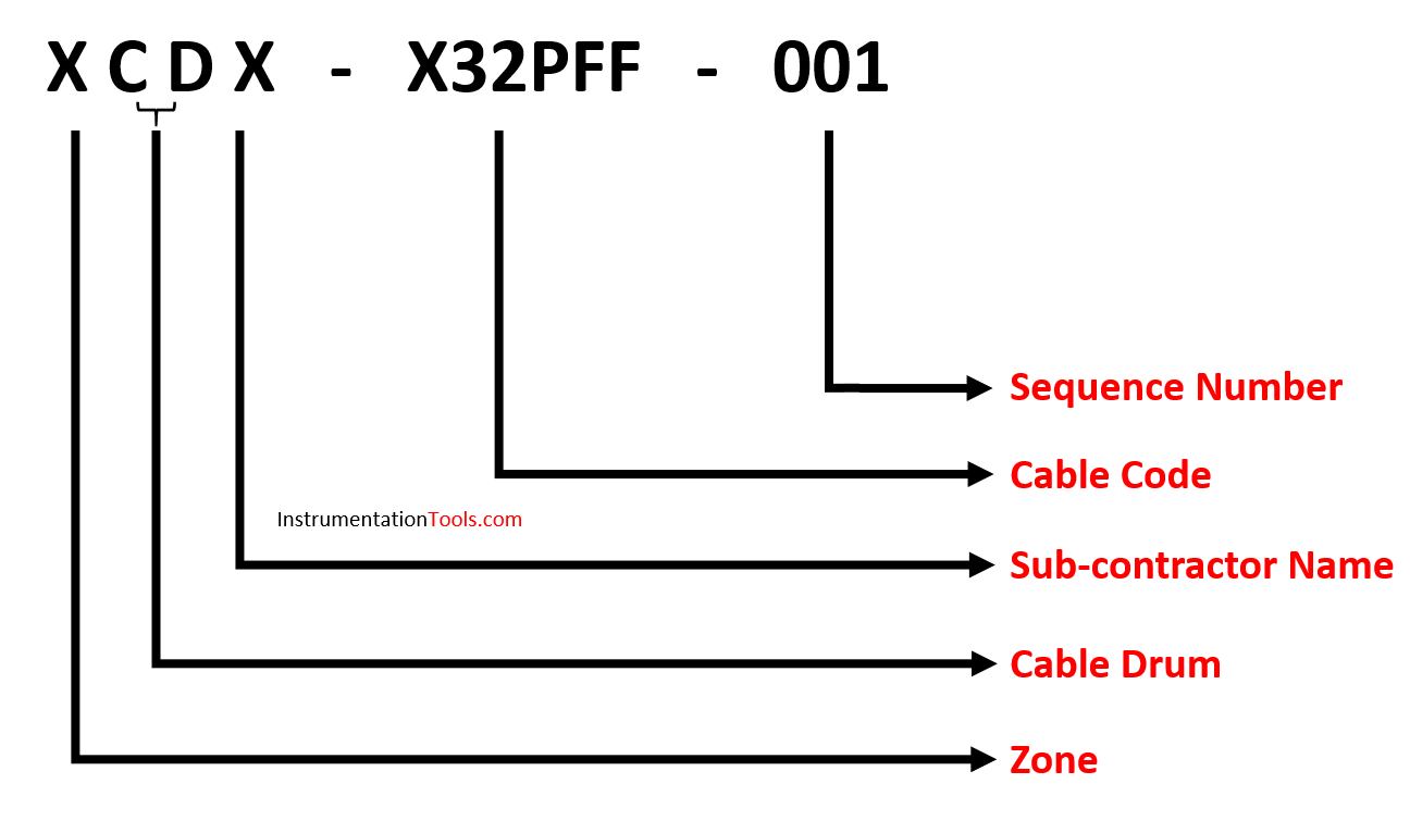
Given above is the basic structure of the Instrument cable drum numbering system.
It includes,
- Zone
- Cable Drum Number
- Sub-Contractor Name
- Cable Code
- Sequence Number
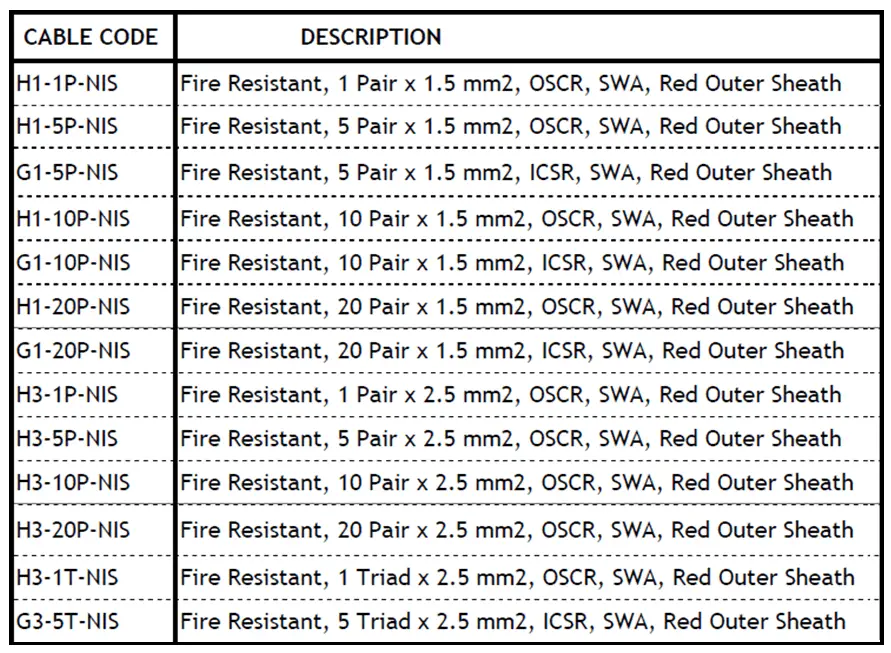
Cable Code
Cable code indicates all details regarding that cable type. There is always a description associated with each cable code.
Given below is an example of cable type and description
Zone details and subcontractor details are entered as per the project execution details.
Cable Drum Schedule
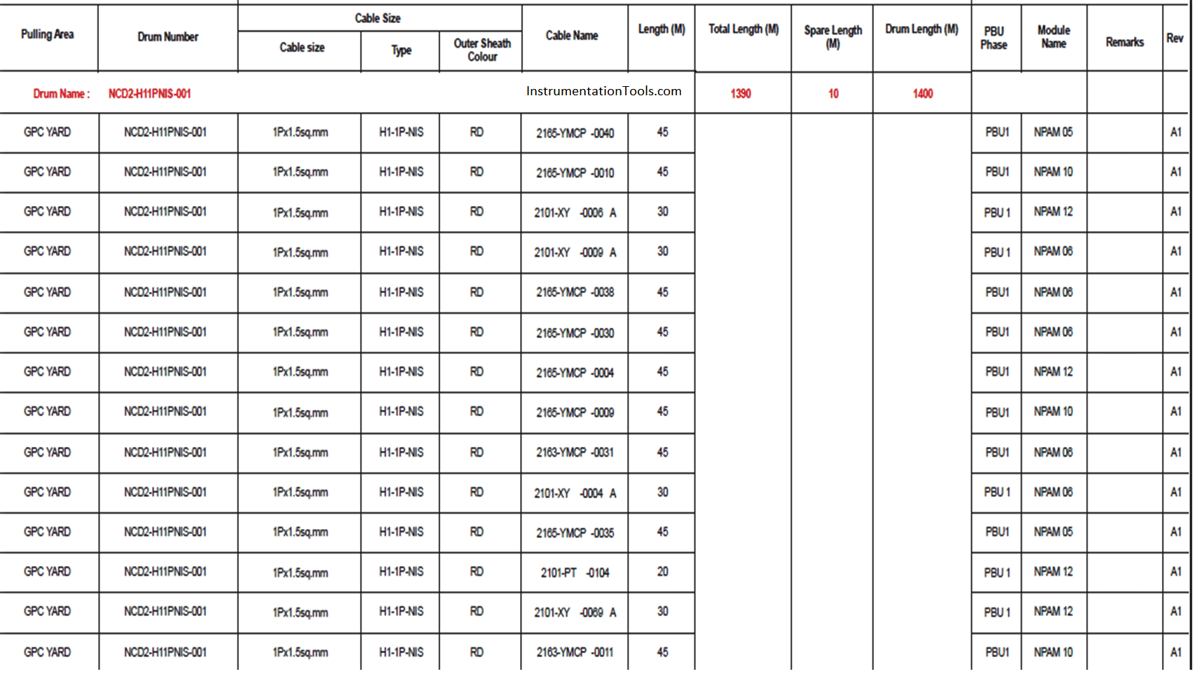
Reference drawings required for the preparation of cable drum schedule are,
- Specification for Instrument Cables
- Cable Drum Tagging Philosophy
- Instrumentation Design Basis
- Instrument Cable Schedule
- Instrument Index
- Fire & Gas Index
Author: Greeshmesh TP
If you liked this article, then please subscribe to our YouTube Channel for Instrumentation, Electrical, PLC, and SCADA video tutorials.
You can also follow us on Facebook and Twitter to receive daily updates.
Read Next: