Cable and Junction Box schedules are deliverables prepared by instrumentation and control design engineers in EPC or EPCM Companies. In this article, we shall learn about the same.
Inputs Required
Below listed references are the required inputs for the preparation of the document “Cable Schedule”.
- P&IDs
- Instrument Index and Instrument I/O List
- I&C Design Basis
- Basic Engineering Design Data
Cable Schedule
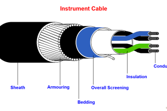
Cable Schedule is a document containing a list of Instrument cables. This document shows cable as well as gland required by each instrument or connection.
The information of the cable schedule consists:
- Cable Number
- Cable Type / Specification
- Cable Size
- Cable Length
- Source and destination termination description
- Cable gland type and size for each incoming cable
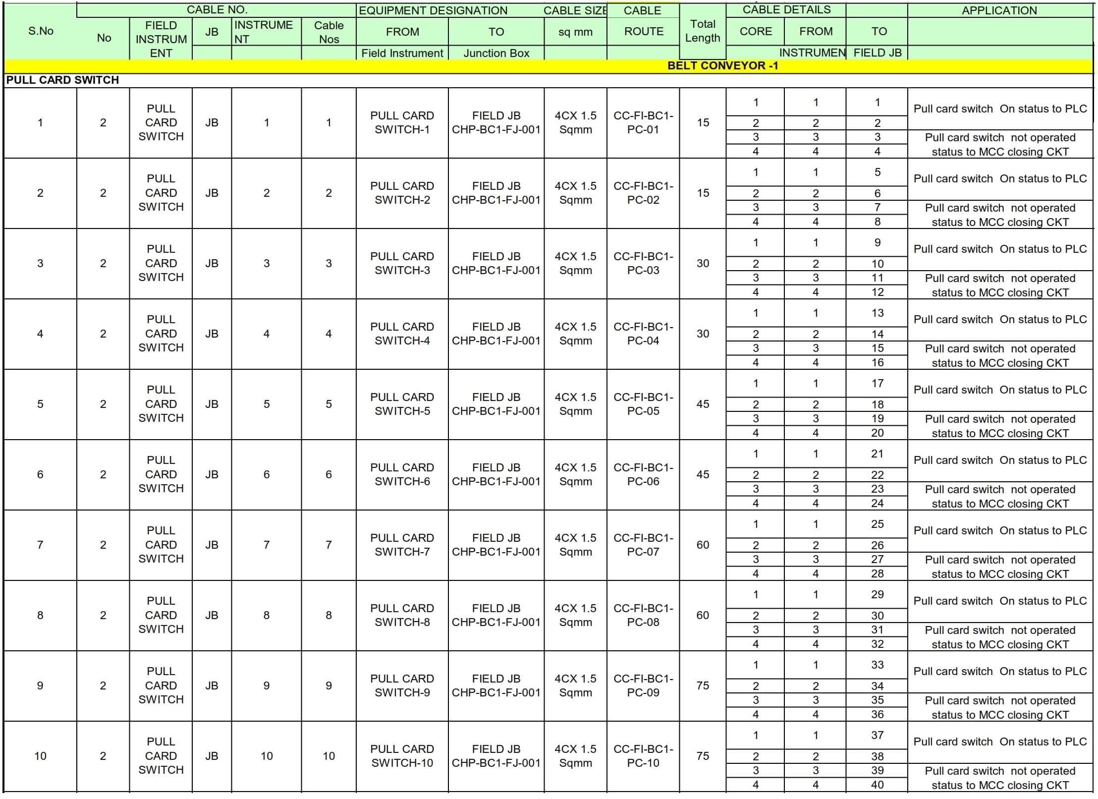
Cable schedule is a reference in preparing Material Take-Off of cable for procurement. However, cable length shown on this document is approximate only. Therefore, there should be a contingency for material procurement to allow spare for cable cutting, unexpected barriers in the field, riser, etc.
Cable schedule will be referred also during the construction phase; however, it is not recommended to cut the cable based on the length information stated on the cable schedule. For actual cutting during installation, the common practice is to pull the cable from its drum and cut it in the field.
This is how a typical Cable schedule looks like.
Junction Box Schedule
First, let us learn about the Junction Box.
The junction box is an enclosure used for cables interconnection between field devices and the control room.
It encloses terminal strips for cable termination. Junction box shall be designed to suit environmental condition where the box will be installed and shall have certification of Ingress Protection code and hazardous area protection which conform to the classified area.
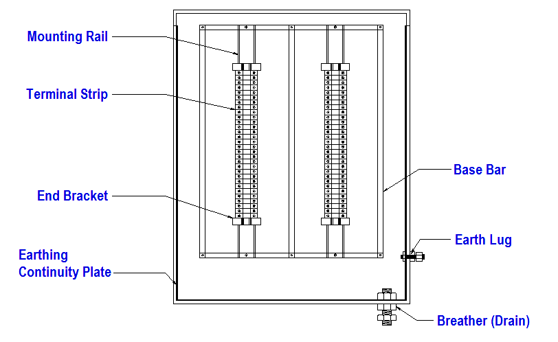
Junction Box consists of the following parts, but not limited to:
- The terminal block which comprises terminal strips for cable connections
- Gland plate (for non-metallic junction box) for cable gland earthing
- An insulated earth bus bar for overall cable screen termination (optional, drain wire could be connected to terminal strip)
- Breather/drain plug
- Mounting Rail complete with end bracket
The typical Junction Box layout
JB Schedule is a document containing a list of instrument JB. This document shows cable as well as gland required by each instrument or connection.
The information of the JB schedule consists:
- JB Number
- JB Type / Specification
- JB Size
- JB Location/Area
- Source and destination termination description
- gland type and size for each incoming cable
JB schedule is a reference in preparing Material Take-Off of JBs for procurement.
JB schedule will be referred also during the construction phase, however, it is not recommended to install JBs based on the location information stated on the JB schedule. For actual installation, the common practice is to refer Location Layout.
Interest to add any further points? Share with us through below comments section.
Author: Kalpit Patel
Read Next:
- Fieldbus Network Topologies
- DCS Wiring Schemes
- Control Valve Accessories
- Instrument Loop Diagram
- Instrumentation Earthing