Inst ToolsInst ToolsInst Tools
  • Courses
  • Automation
    • PLC
    • Control System
    • Safety System
    • Communication
    • Fire & Gas System
  • Instrumentation
    • Design
    • Pressure
    • Temperature
    • Flow
    • Level
    • Vibration
    • Analyzer
    • Control Valve
    • Switch
    • Calibration
    • Erection & Commissioning
  • Interview
    • Instrumentation
    • Electrical
    • Electronics
    • Practical
  • Q&A
    • Instrumentation
    • Control System
    • Electrical
    • Electronics
    • Analog Electronics
    • Digital Electronics
    • Power Electronics
    • Microprocessor
  • Request
Search
  • Books
  • Software
  • Projects
  • Process
  • Tools
  • Basics
  • Formula
  • Power Plant
  • Root Cause Analysis
  • Electrical Basics
  • Animation
  • Standards
  • 4-20 mA Course
  • Siemens PLC Course
Reading: UPS Working Principle and Types – Offline and Online UPS Systems
Share
Font ResizerAa
Inst ToolsInst Tools
Font ResizerAa
  • Courses
  • Design
  • PLC
  • Interview
  • Control System
Search
  • Courses
  • Automation
    • PLC
    • Control System
    • Safety System
    • Communication
    • Fire & Gas System
  • Instrumentation
    • Design
    • Pressure
    • Temperature
    • Flow
    • Level
    • Vibration
    • Analyzer
    • Control Valve
    • Switch
    • Calibration
    • Erection & Commissioning
  • Interview
    • Instrumentation
    • Electrical
    • Electronics
    • Practical
  • Q&A
    • Instrumentation
    • Control System
    • Electrical
    • Electronics
    • Analog Electronics
    • Digital Electronics
    • Power Electronics
    • Microprocessor
  • Request
Follow US
All rights reserved. Reproduction in whole or in part without written permission is prohibited.
Inst Tools > Blog > Electrical Basics > UPS Working Principle and Types – Offline and Online UPS Systems

UPS Working Principle and Types – Offline and Online UPS Systems

In this article, you will learn the working principle of UPS with block diagrams. The most common types are offline and online UPS systems.

Last updated: September 28, 2022 4:09 pm
Viral Nagda
Electrical Basics PLC Tutorials
1 Comment
Share
5 Min Read
SHARE

In this article, you will learn the working principle of UPS with block diagrams. The most common types are offline and online UPS systems.

Contents
Offline UPS Working PrincipleOnline UPS Working Principle

UPS stands for the uninterrupted power source. As the name implies, it is used to provide a continuous power supply to the load using an automatic switching method; to prevent the device and equipment from damage or preventing the plant from going into a shutdown mode.

There are many devices that require a safe shutdown for proper operation; otherwise, sudden power loss can damage the equipment.

A simple example can be considered a computer. Not properly shutting it down due to abrupt power off can corrupt its operating system or cause some other damage.

A UPS in this case will provide power for some time; so that the device shuts off properly. Though the time is short; it will provide a safe shut down for a device.

 A UPS takes AC supply, stores it in batteries and these batteries then feed the power back to the load device in case of mains power failure. This is the basic working of UPS.

Every UPS has a semiconductor static switch, which is used to switch power between the main AC supply and batteries to the load. Failure of this switch can cause the UPS to be worthless because it will damage the working of UPS.

The basic components of UPS are – a rectifier (conversion of AC to DC for feeding batteries), inverter (conversion of DC to AC for feeding load), battery (for providing DC power to the inverter), and a semiconductor switch for switching load transfer between mains AC supply and inverter supply.

Let us understand some types of UPS and their working:

Offline UPS Working Principle

The Offline UPS is the simplest one of all types. As you can see, the load is normally supplied power from mains AC supply.

The AC supply is also used to charge the battery bank. The battery is used to feed DC power to the inverter; for converting it to AC supply.

Offline UPS

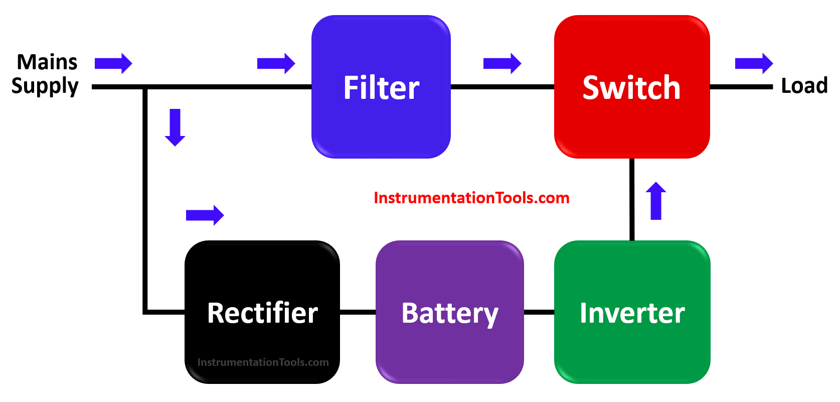
When the mains supply fails, the switch will automatically cut off power from it and supply power to the load from the inverter circuit.

The switching time is usually around 25 milliseconds. This type of inverter is the least expensive one; because the main issue is the large switching time.

The offline UPS is also called standby UPS.

Online UPS Working Principle

The online UPS is a complex type of UPS. As you can see, the load is normally supplied power from the inverter.

The AC supply is used to charge the battery bank through a rectifier, as well as supply DC power to the inverter.

Online UPS

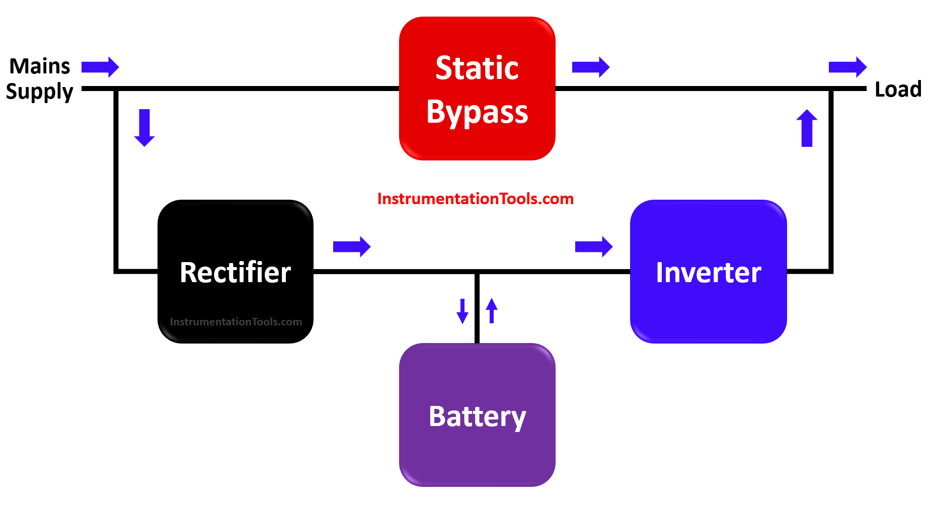
When the main supply fails, the battery will automatically supply power to the inverter. The rectifier will be bypassed in this case.

One more added feature is the addition of a static bypass switch. When the UPS fails (means failure of the inverter, battery, or rectifier), this switch is turned on which supplies direct AC power to the load as shown in the above figure.

The switching time is usually very low (around 4-5 milliseconds; between inverter circuit and static bypass switch). Apart from this, the online UPS is very fast in operation; because the battery immediately supplies power to the inverter in case of mains AC failure.

The output type of UPS is a pure sinusoidal waveform and is a perfect replacement for the mains AC supply in case of power failure. It will provide temporary power to the load for a time based on battery backup or resumption of AC power.

In this way, we understood the working of UPS.

If you liked this article, then please subscribe to our YouTube Channel for Instrumentation, Electrical, PLC, and SCADA video tutorials.

You can also follow us on Facebook and Twitter to receive daily updates.

Read Next:

  • DOL Starter
  • Servo Motor Drives
  • Cathodic Protection
  • Motor Control Center
  • What is a Soft Starter?
Don't Miss Our Updates
Be the first to get exclusive content straight to your email.
We promise not to spam you. You can unsubscribe at any time.
Invalid email address
You've successfully subscribed !

Continue Reading

Converter Instruction in Siemens PLC Programming
Why different PLC Programming Languages were Developed?
Difference Between PLC and SCADA
What are Ground Fault and Earth Fault?
What is a Motor Disconnector Switch? – Purpose, Principle, Factors
Difference between Current Transformer and Potential Transformer
Share This Article
Facebook Whatsapp Whatsapp LinkedIn Copy Link
Share
1 Comment
  • Fekadu says:
    April 13, 2022 at 11:17 pm

    please send me materials/books/ppt/pdf

    Reply

Leave a Reply Cancel reply

Your email address will not be published. Required fields are marked *

Stay Connected

128.3kFollowersLike
69.1kFollowersFollow
210kSubscribersSubscribe
38kFollowersFollow

Categories

Explore More

Allen Bradley PLC to PLC Communication in Studio 5000
Residual Current Circuit Breaker (RCCB)
PLC Program for Automatic Parameter Initialization When Power UP
Ladder Logic Example with Timers
How to Control VFD with PLC using Ladder Logic
PLC Logic GATE Program
What is Interface Module in Siemens PLC?
Difference Between Electric Field and Magnetic Field

Keep Learning

PLC program pushbutton switches

PLC Permissive for Motor Control

TIA Portal Options

How to Troubleshoot Siemens PLC Programs?

Why Use Normally-Closed Contact for Stop Buttons

Why Use Normally-Closed Contact for Stop Buttons?

100 Electronics and Electrical Projects for Engineering Students

100 Electronics and Electrical Projects for Engineering Students

OB and FB Blocks in Siemens PLC

Procedure for Siemens S7-300 Download from PC to PLC

PLC Programming Example on Bottle Line Control

PLC Programming Example on Bottle Line Control

Electrical Conduit Seal

Assembling an Electrical Conduit Seal

Electrical Feeder Automation in Smart Grid

Electrical Feeder Automation in Smart Grid

Learn More

CPU Communication Ports in Siemens PLC

Types of CPU Communication Ports in Siemens PLC

PLC Memory Organization - Data Files and Program Files

PLC Memory Organization – Data Files and Program Files

transistor-emitter-bias

Transistor Emitter Bias

Symbol of MOS Controlled Thyristor

MCT (MOS Controlled Thyristor) – Symbol, Working, Characteristics, Advantages

Electrical Machines Questions and Answers

Synchronous Machine Stability Questions

Inductive proximity switches

How to Connect Proximity Switch (Source Type) to Make LED ON ?

Difference Between Open Circuit and Close Circuit

Difference Between Open Circuit and Close Circuit

Lamp Counter Logic

Function Block (FB) for Motor Control Logic

Menu

  • About
  • Privacy Policy
  • Copyright

Quick Links

  • Learn PLC
  • Helping Hand
  • Part Time Job

YouTube Subscribe

Follow US
All rights reserved. Reproduction in whole or in part without written permission is prohibited.
Welcome Back!

Sign in to your account

Username or Email Address
Password

Lost your password?