Inst ToolsInst ToolsInst Tools
  • Courses
  • Automation
    • PLC
    • Control System
    • Safety System
    • Communication
    • Fire & Gas System
  • Instrumentation
    • Design
    • Pressure
    • Temperature
    • Flow
    • Level
    • Vibration
    • Analyzer
    • Control Valve
    • Switch
    • Calibration
    • Erection & Commissioning
  • Interview
    • Instrumentation
    • Electrical
    • Electronics
    • Practical
  • Q&A
    • Instrumentation
    • Control System
    • Electrical
    • Electronics
    • Analog Electronics
    • Digital Electronics
    • Power Electronics
    • Microprocessor
  • Request
Search
  • Books
  • Software
  • Projects
  • Process
  • Tools
  • Basics
  • Formula
  • Power Plant
  • Root Cause Analysis
  • Electrical Basics
  • Animation
  • Standards
  • 4-20 mA Course
  • Siemens PLC Course
Reading: Location of Measurement Displays
Share
Notification Show More
Font ResizerAa
Inst ToolsInst Tools
Font ResizerAa
  • Courses
  • Design
  • PLC
  • Interview
  • Control System
Search
  • Courses
  • Automation
    • PLC
    • Control System
    • Safety System
    • Communication
    • Fire & Gas System
  • Instrumentation
    • Design
    • Pressure
    • Temperature
    • Flow
    • Level
    • Vibration
    • Analyzer
    • Control Valve
    • Switch
    • Calibration
    • Erection & Commissioning
  • Interview
    • Instrumentation
    • Electrical
    • Electronics
    • Practical
  • Q&A
    • Instrumentation
    • Control System
    • Electrical
    • Electronics
    • Analog Electronics
    • Digital Electronics
    • Power Electronics
    • Microprocessor
  • Request
Follow US
All rights reserved. Reproduction in whole or in part without written permission is prohibited.
Inst Tools > Blog > Instrumentation Design > Location of Measurement Displays

Location of Measurement Displays

Last updated: December 29, 2016 5:26 am
Editorial Staff
Instrumentation Design
No Comments
Share
3 Min Read
SHARE

The measurement is displayed for observation by plant personnel.  Typically, the display uses analog principles, which means that the display presents the measurement as a position in a graphical format, which could, for example, be the height of a slide bar or the position of a pointer.  Often, the value is displayed as a line on a trend plot that provides the values for some time in the past.

In addition, the measurement can be displayed as a digital number to provide more accuracy for calibration.  Finally, measurements that are transmitted to a digital control system can be stored in a historical database for later recall and for use in calculating important parameters useful in monitoring process behavior, for example, reactor yields or heat transfer coefficients.

The engineer must ensure that the measurements are displayed where needed by personnel.  Several common approaches are briefly summarized in the following.

Local display – A sensor can display the measurement at the point where the sensor is located.  This information can be used by the people when monitoring or working on the equipment.  A measurement that has only local display involves the lowest cost, because the cost of transmission and interfacing to a digital system are not required.  Note that no history of these measurements is available unless people record the values periodically.

Local panel display – Some equipment is operated from a local panel, where sensors associated with a unit are collected.  This enables a person to startup, shutdown and maintain the unit locally.  This must be provided for units that require manual actions at the process during normal operation (loading feed materials, cleaning filters, etc.) or during startup and shutdown.  Usually, the values displayed at a local panel are also displayed at a centralized control room.

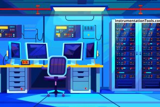
Centralized control room – Many processes are operated from a centralized control room that can be located a significant distance (e.g., hundreds of meters) from the process.  The measurement must be converted to a signal (usually electronic) for transmission and be converted to a digital number when interfaced with the control system.  A centralized control system facilitates the analysis and control of the integrated plant.

Remote monitoring – In a few cases, processes can be operated without a human operator at the location.  In these situations, the measurements are transmitted by radio frequency signals to a centralized location where a person can monitor the behavior of many plants.  Typical examples are remote oil production sites and small, safe chemical plants, such as air separation units.

Don't Miss Our Updates
Be the first to get exclusive content straight to your email.
We promise not to spam you. You can unsubscribe at any time.
Invalid email address
You've successfully subscribed !

Continue Reading

Heat Tracing Problems
Field Instruments Selection Aid
Difference between Intrinsic Safe and Non-Intrinsic Safe Cables
All About Vortex Flow Meters
Level Instruments General Specifications
How to Select a pH or ORP Meter
Share This Article
Facebook Whatsapp Whatsapp LinkedIn Copy Link
Share
Leave a Comment

Leave a Reply Cancel reply

Your email address will not be published. Required fields are marked *

Stay Connected

128.3kFollowersLike
69.1kFollowersFollow
210kSubscribersSubscribe
38kFollowersFollow

Categories

Explore More

Instrumentation and Electrical Teams Interactions (Detail Design Engineering)
Why 4-20 mA Standard is so popular ?
What is a Mimic Panel ?
Switch or Transmitter
Instrumentation and Control Project Packages – Detail Engineering
Explain Operation of the Lamp Circuit ?
As per Process Conditions, Find out the Circuit Components Status ?
Tagging Philosophy for Junction Box, Cable, and Cable Drum

Keep Learning

Instrument Air (IA) System

Process Design of Instrument Air System

Relay Permissive and interlock circuits

Basics of Permissive and Interlock Circuits

Pneumatic Piping Design and Specification

Pneumatic Piping Design and Specification

Panel Ground Noise

Floating Vs. Grounded Voltage

Instrumentation and Control General Specifications

Instrumentation and Control (I&C) General Specifications

Selection Criteria of PH Analyzer

Selection Criteria of pH Analyzers

Switch Contact checking with oscilloscope

What is Contact bounce ?

Voting System in PLC

Voting Concept in Package Safety System

Learn More

PLC Controlling a Motor

PLC Motor Control Ladder Logic Programming

Electrical Welding Multiple Choice Questions and Answers

Electrical Welding Multiple Choice Questions and Answers (MCQ)

stepper motors Animation

Fundamentals of DC Motor Animation

HART Communication Interview Questions

HART Communication Interview Questions and Answers

PLC Programming for Pumping and Draining System

PLC Programming for Pumping and Draining System

Fixed Gas Detectors vs. Portable Gas Detectors

Fixed Gas Detectors vs. Portable Gas Detectors

different types of threads based on 4 standards

Different Types of Threads based on 4 Standards

What can you do with an Engineering Degree

What Can You Do with an Engineering Degree?

Menu

  • About
  • Privacy Policy
  • Copyright

Quick Links

  • Learn PLC
  • Helping Hand
  • Part Time Job

YouTube Subscribe

Follow US
All rights reserved. Reproduction in whole or in part without written permission is prohibited.
Welcome Back!

Sign in to your account

Username or Email Address
Password

Lost your password?