In this article, we are sharing the basic concepts of PLC and DCS control systems Wiring Diagrams for Digital Input (DI), Digital Output (DO), Analog Input (AI), and Analog Output (AO) signals.
Note that these diagrams are without a Barrier or isolator, fuses, or surge protector to keep them very simple and understandable.
Also Check: PLC and SCADA Training courses
Wiring Diagrams of PLC and DCS
The below list shows the basic types of wiring connections available for DI, DO, AI, and AO Signals:
Digital Input (DI) Signals
- Single-wire Connection
- Two-wire connection
- Two-wire connection with Line Monitoring
- DI with Relay – Wet Contact
- DI with Relay – Dry Contact
Digital Output (DO) Signals
- Two-wire connection
- DO with Relay – Wet Contact
- DO with Relay – Dry Contact
- Interfacing with Other Control Systems
- DO with Line Monitoring
Analog Input (AI) Signals
- Single-wire connection
- Two-wire connection
- Three-wire connection
- Interfacing with other control systems
Analog Output (AO) Signals
- Two-wire connection
Digital Input Signals to PLC / DCS
Input type with respect to the system
Terminal type/connection, Shield is not shown for simplicity.
Two-Wire Connection with Input Card

The two-wire connection is used to connect field instruments like limit switches, proximity switches, motor run feedback, Pump start permissive, etc.
Two-Wire Connection with Line Monitoring

When we need additional protection measures to identify the short circuit and open circuit of digital inputs then we use this configuration.
Generally, a pair of resistors are used at the terminations of field instruments or in some cases at marshaling cabinets.
This works on the principle of change in resistance. During the Open circuit, both resistors R1 & R2 are in line, so we will get some loop resistance, say “x” ohms. During a Short Circuit, resistor R1 becomes zero and we will get some other loop resistance, say “y” ohms.
The input cards are designed such that they will identify the signal status and differentiate these conditions, alert the system engineers with alarms.
DI Card with Single Wire Connection

DI With Relay – Wet Contact (For Coil)

This configuration is used when we need an additional power supply for the field instruments, motor control centers, etc.
Generally, in marshaling cabinets, we make the necessary wiring arrangements as per the application requirements.
We are using the additional power supply in the marshaling cabinet (or at the control room side), so we are calling this a WET Contact.
When the field instrument is in an Open state then the relay will not be energized thus DI card doesn’t have the return signal, so it will be considered as OFF state.
When the field instrument is in a closed state then the relay will be energized thus DI card has the return signal, so it will be considered as ON state.
This external relay power supply is called as interrogation voltage.
The interrogation voltage from the panel can be 24 VDC, 110 VDC, etc.
What is the Interrogation Voltage?
Interrogation voltage is a term used in relation to digital inputs of PLC or DCS control systems.
When there is some activity in the digital inputs like limit switch activation, then there will be a change in input state from open to close or close to open depending on the type of contact used in the limit switch.
Now we need to interrogate (identify) the state of these contacts (open/close) using a voltage. So we send a voltage (12VDC, 24VDC, 110 VDC, etc) to the limit switch and receive the signal back when the limit switch is in the closed state.
The PLC reads these signals and takes the action as per its logic. This voltage is called as interrogation voltage.
DI With Relay – Dry Contact (For Coil)
")
We are NOT using any additional power supply in the marshaling cabinet (or at the control room side), so we are calling this a DRY Contact.
When the field instrument is in an Open state then the relay will not be energized thus DI card doesn’t have the return signal, so it will be considered as an OFF state.
When the field instrument is in a closed state then the relay will be energized thus DI card has the return signal, so it will be considered as ON state.
Example: Motor Run Feedback.
The interrogation voltage from voltage can be 24 VDC, 110 VDC, etc.
Digital Output Signals from PLC / DCS
Output type with respect to system terminal type/connection.
The shield is not shown for simplicity reasons.
Two-wire connection with Output Card

This configuration is used to control digital instruments like Solenoid Valves.
We may use Barriers after the DO card for safety reasons. Barriers are not shown in the diagrams.
When the DO command is given then the respective voltage will go to the field instrument and it will be energized.
When the DO command is taken back then the respective voltage will be stopped to the field instrument and it will be De-energized.
DO With Relay – Wet Contact

We use an additional power supply (24 VDC, 110 VDC, 230 VAC, etc) in the marshaling cabinet (at the control room side) to power the field instrument.
This configuration is generally used for hooters, beacons, high-power solenoid valves, etc.
DO With Relay – Dry Contact

This configuration is generally not preferred.
Interfacing with Other Control Systems (DCS/PLC/ESD)
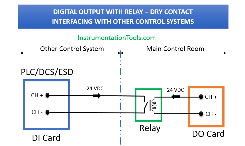
This configuration is widely used in industries for interfacing with third-party control systems.
DO with Line Monitoring
The line monitoring for digital output cards is also possible but up to relay coil and/or up to field shall be confirmed by the system vendor.
Analog Input Signals to PLC / DCS
Shields are not shown for simplicity reasons.
The 4-wire instruments require an additional power supply.
Two-wire Connection with AI Card

This configuration is used to connect two-wire transmitters like PT, TT, FT, LT, etc.
We may use barriers also after the AI card for safety precautions. These are not shown in the diagrams.
AI Card with Single Wire Connection

For Interfacing with Other Control Systems
DCS AO to PLC AI

Both side’s Active will not work.
PLC AO to DCS AI

Both sides Active will not work
Both sides Passive will not work.
Analog Output Signals

Author: Jatin Katrodiya
Join the Discussion! Share your thoughts about the basic wiring diagrams using the comments section.
Missed any?
If you liked this article, then please subscribe to our YouTube Channel for PLC and SCADA video tutorials.
You can also follow us on Facebook and Twitter to receive daily updates.
Read Next:
- Control System Architecture
- Industrial Control Systems
- Difference between DCS & PLC
- Control System Security
- What is PLC Redundancy?
- DCS System Basics


DI or discrete/digital input is the type of PLC input which used to read the status of digital input devices. The Digital input device only has 2 statuses, ON or OFF. ON state mean PLC DI point received status in form of electrical power (can be 24 VDC, 120 VAC, etc.) and OFF state mean PLC DI point received no power from devices. An example of a Digital input device is a switch.
DO or discrete/digital output is the type of PLC output which used to control digital output devices. Digital output devices only have 2 status, ON or OFF. ON command mean PLC DO point send command in form of electrical power (24 VDC, 120 VAC, etc.) and OFF command means PLC DO send no power to devices. An example of digital output devices is a relay.
AI or analog input is the type of PLC input which used to read the value from the sensor. AI receives value from the sensor in the form of electrical current (4-20 ma) or electrical voltage (1-5 V). ADC (Analog to Digital Converter) inside PLC will convert current or voltage to a digital value in the form of 16 or 12-bit word data to further process. An example of a sensor is the temperature sensor. The temperature sensor will measure temperature and send measurement value to the AI channel in the form of current or voltage.
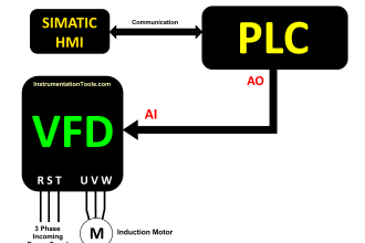
AO or analog output is the type of PLC output which used to control analog devices. AO sends a command to the device in the form of electrical current (4 – 20 mA) or electrical voltage. DAC (Digital to Analog Converter) inside PLC will convert a digital value (12 bit or 16-bit word data resulted from PLC calculation) to current or voltage and send it to a controlled device through the AO channel. An example of an AO device is the control valve, PLC could control opening percentage of the control valve with send 4 – 20 mA current which represents 0 – 100% open command.
Nice concept
Excellent explanation in very simple way possible. Thank you very much for valuable information.
Sir very nice information
Yes, following is missed:
“Analog Input (AI) -Three-wire connection”
Sir you’re great and help us to understand