3D modeling is the process of developing a mathematical, wireframe/solid representation of any surface of an object in three dimensions via specialized software by manipulating edges, vertices, and polygons in a simulated 3D space.
The created object is known as a 3D model and these 3-dimensional models are utilized in an assortment of ventures.
Advantages of 3D Modeling
The advantages of 3D modeling are as follows:
- Easy to understand
- 3D design is almost 45% faster than 2D design. That really helps in saving lot of time
- We can have to create a legitimate model of a plant by using software which provides accurate depiction of that plant which can be understood by everyone from any angle.
- 3D design layouts helps designers from different disciplines to work at same time to develop a complete model.
- There is a high chance for occurring clashes while designers from different disciplines working together at same time. The clash check options inside modeling/review software is really helpful in detecting these clashes.
- We can extract cable tray layout, junction box layout, instrument location layout, bill of materials, etc easily using 3D modeling software.
Instrumentation Modeling Softwares
The popular list of instrumentation modeling software is as follows:
- PDMS (Plant Design & Management System) by Aveva
- E3D (Everything 3D) by Aveva
- PDS (Plant Design System) by Intergraph
- SP3D (Smart Plant 3D) by Intergraph
Modeling Review Softwares
- Navis Works by Autodesk
- Smart Plant Review by Intergraph
Review software helps the construction team to build the plant easily as per the drawing. We can’t have to make any changes to the model using review software.
We can measure distances, view tag numbers, pipe size, and can have to rotate the model as per our needs using review software.
Review software is really helpful in finding the clashes /interferences within the model.
Documents Required for Instrumentation Modeling
Some of the important documents required for instrumentation 3D modeling are as follows:
- Piping & Instrumentation Diagram (P&ID)
- Equipment Model Library
- Typical Hook-up Drawing
- Fire & Gas Detector Layout
- Cable Tray/Trench Layout
Also Read: Instrumentation Design Engineer
Responsibilities of an Instrumentation 3D Modeler
The below list shows some of the instrumentation engineers’ responsibilities for preparing the 3D models.
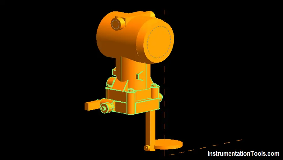
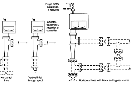
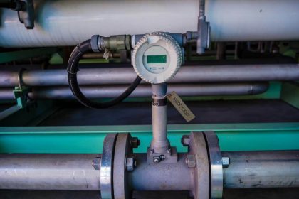
Modeling of Process Instruments
The example 3D model of a process instrument is shown below figure.
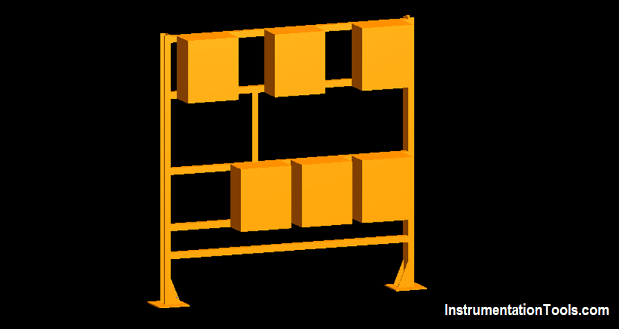
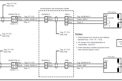
Modeling of Junction Boxes
The example 3D model of a junction box is shown below figure.
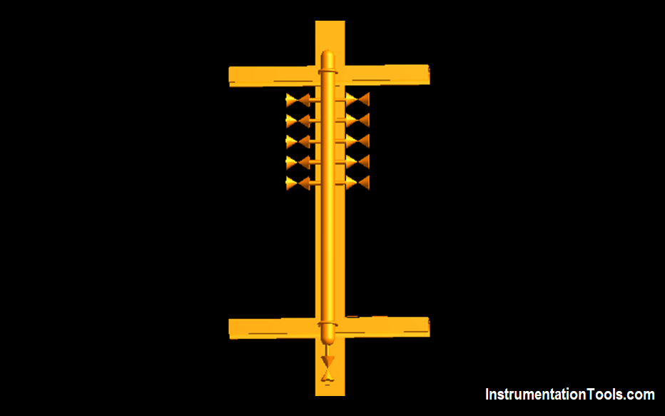
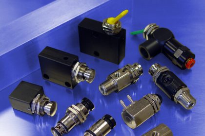
Modeling of Air Manifolds
The example 3D model of an instrument air manifold is shown below figure.
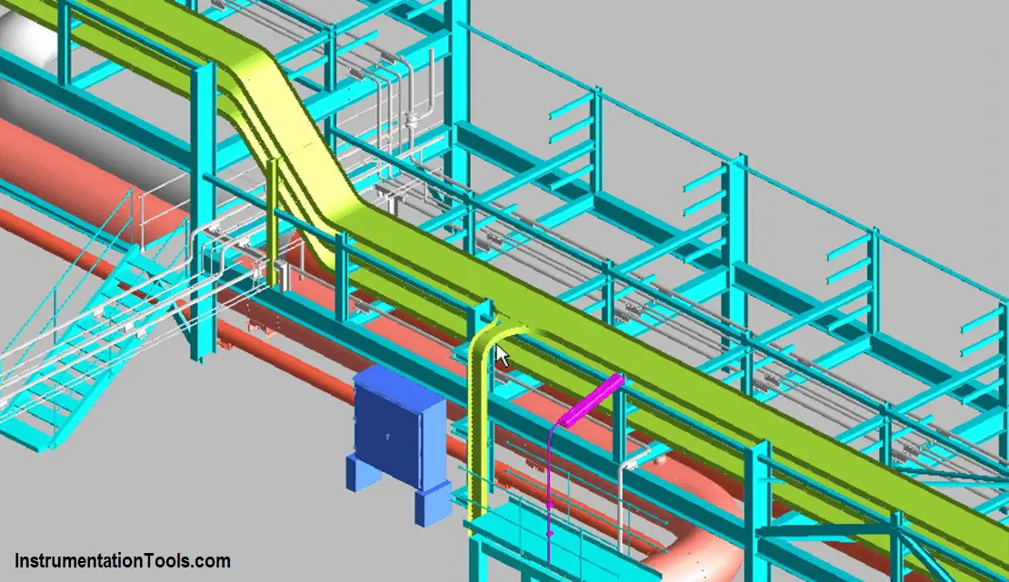
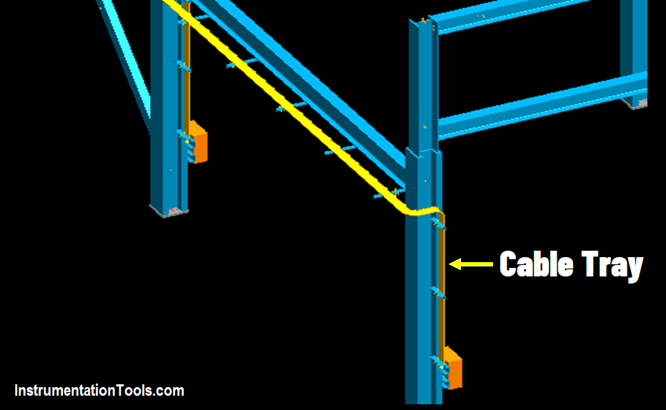
Modeling of Instrument Cable Trays
The example 3D model of an instrument cable tray is shown below figure.
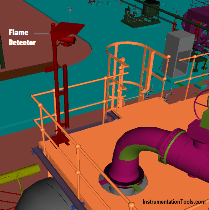
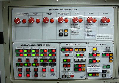
Modeling of Fire and Gas Detectors
The example 3D model of a flame detector is shown below figure.
Modeling of Instrument Cable Trenches
The example 3D model of a cable trench is shown below figure.
Modeling of local panels, instrument cabinets, pipe sleeves, and instrument ducts also come under the job responsibility of an instrumentation 3D modeler.
Piping Design Engineers
Other instrumentation entities are modeled by piping designers such as
- Control valve,
- Shutdown valve,
- Pressure relief valves,
- Air volume tank,
- Analyzer shelters,
- Instrument skids,
- Orifice plates,
- Inline flow meters, etc
Also Read: List of Instrumentation Documents
Instrumentation Deliverables generated from 3D Modeling
We can generate a lot of instrumentation deliverables (documents, layouts) which helps in project execution from 3D modeling of that plant.
Major deliverables are
- Instrument Location Layout
- Cable Tray Layout
- Junction Box Location Layout
- Control Room Equipment Layout
- Fire & Gas Detector Layout
We can also generate a material take-off list, bill of materials, bill of quantity, installation drawing from 3D modeling.
Author: Greeshmesh TP
If you liked this article, then please subscribe to our YouTube Channel for Instrumentation, Electrical, PLC, and SCADA video tutorials.
You can also follow us on Facebook and Twitter to receive daily updates.
Read Next:
- SIL Verification
- Tagging Philosophy
- Instrument Tapping Points
- What is SAMA Diagram?
- Level Gauge Design


Could you give me the 3D model of devices in instrumentation system?