Inst ToolsInst ToolsInst Tools
  • Courses
  • Automation
    • PLC
    • Control System
    • Safety System
    • Communication
    • Fire & Gas System
  • Instrumentation
    • Design
    • Pressure
    • Temperature
    • Flow
    • Level
    • Vibration
    • Analyzer
    • Control Valve
    • Switch
    • Calibration
    • Erection & Commissioning
  • Interview
    • Instrumentation
    • Electrical
    • Electronics
    • Practical
  • Q&A
    • Instrumentation
    • Control System
    • Electrical
    • Electronics
    • Analog Electronics
    • Digital Electronics
    • Power Electronics
    • Microprocessor
  • Request
Search
  • Books
  • Software
  • Projects
  • Process
  • Tools
  • Basics
  • Formula
  • Power Plant
  • Root Cause Analysis
  • Electrical Basics
  • Animation
  • Standards
  • 4-20 mA Course
  • Siemens PLC Course
Reading: 15 Loop Diagram Questions
Share
Font ResizerAa
Inst ToolsInst Tools
Font ResizerAa
  • Courses
  • Design
  • PLC
  • Interview
  • Control System
Search
  • Courses
  • Automation
    • PLC
    • Control System
    • Safety System
    • Communication
    • Fire & Gas System
  • Instrumentation
    • Design
    • Pressure
    • Temperature
    • Flow
    • Level
    • Vibration
    • Analyzer
    • Control Valve
    • Switch
    • Calibration
    • Erection & Commissioning
  • Interview
    • Instrumentation
    • Electrical
    • Electronics
    • Practical
  • Q&A
    • Instrumentation
    • Control System
    • Electrical
    • Electronics
    • Analog Electronics
    • Digital Electronics
    • Power Electronics
    • Microprocessor
  • Request
Follow US
All rights reserved. Reproduction in whole or in part without written permission is prohibited.
Inst Tools > Blog > Instrumentation Design > 15 Loop Diagram Questions

15 Loop Diagram Questions

Loop Diagram helps us to read the wiring connections from field instruments to the system cabinet. Find the top 15 Loop Diagram Questions here.

Last updated: September 22, 2020 10:05 am
Editorial Staff
Instrumentation Design Instrumentation Interview Questions
13 Comments
Share
3 Min Read
SHARE

Loop Diagram helps us to read the wiring connections from field instruments to system cabinet. Find the top 15 Loop Diagram Questions here.

Read: What are Loop DIagrams?

Examine this loop diagram, and answer the following questions:

Loop Diagram

Loop Diagram

Click on the image to zoom

Question 1:

What type of control loop is represented in this diagram? In other words, what is the process variable, and how is this process variable manipulated?

Question 2:

What is the calibrated range of the sensing instrument?

Question 3:

How are physical locations for wire connection points declared in this diagram?

Question 4:

Assuming the resistor inside the DCS input card is 250 ohms, calculate the amount of voltage between terminals 23 and 24 at a transmitter signal value of 50%.

Answer:  At a 50% signal (12 mA in a 4-20 mA range), the voltage dropped between terminals 23 and 24 will be 21 volts.

Question 5:

Identify where wires are part of a larger, multi-conductor cable, and identify how those wires are distinguished from all the others in that cable.

Question 6:

Identify the convention used to label wire pairs for each field instrument. In other words, how can a person tell whether a certain wire pair is going out to the transmitter, the indicator, or the control valve?

Question 7:

Identify at least two different ways you could measure the transmitter’s signal without interrupting the 4-20 mA current signal to the flow controller.

Question 8:

Explain why interrupting the loop’s continuity is a bad thing if the control system is operating, controlling a live process.

Question 9:

What do the letters “FI” and “FO” stand for? Are these labels ISA-standard?

Question 10:

Is FT-733 self-powered or loop-powered? How can you tell?

Question 11:

Sketch arrows showing the direction of electric current in each wire (using conventional flow notation), identifying each component as being either a source or a load.

Question 12:

Identify all the effects of pair 4 within cable ISOM-18 failing open and failing shorted.

Question 13:

Identify all the effects of cable FI-733 failing open.

Question 14:

Identify all the effects of pair 5 within cable ISOM-18 failing open and failing shorted.

Question 15:

When we use loop diagrams for troubleshooting? Explain with some examples.

Share your answers with us through comments.

Read Next:

  • HART Communicator Analysis
  • Instrumentation documents
  • What are Instrument Errors?
  • Configure a Smart Transmitter
  • What is NAMUR NE 43?

Credits: Tony R. Kuphaldt

Don't Miss Our Updates
Be the first to get exclusive content straight to your email.
We promise not to spam you. You can unsubscribe at any time.
Invalid email address
You've successfully subscribed !

Continue Reading

Electrical Signal and Control Wiring
Draw Wiring of a Pressure Switch to control two lamps
What is FAT and SAT? Difference between them
Detail Design Engineering Competency Aspects
Control Valves Multiple Choice Questions
Air Cylinder Consumption Calculation for Control Valves
Share This Article
Facebook Whatsapp Whatsapp LinkedIn Copy Link
Share
13 Comments
  • afzal says:
    January 23, 2020 at 9:07 pm

    answer for question 1

    this diagram is repersenting a closeloop, and flow is the process variable . and the process variable can be manupulated by (fv-733)

    answer for question 2

    the calibration range of the sensing element is 0-125 wc

    Reply
  • James Robles says:
    January 25, 2020 at 10:24 am

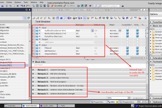
    I have a question. What software is used to draw loop diagrams?? I have never found how to draw them. Is it auto CAD? Is it Visio? Is it MS excel?

    Reply
    • Vinoth Baskaran says:
      March 19, 2020 at 10:41 am

      It depends on client requirement during EPC stage, In General Loop Diagrams are generated in Smart Plant Instrumentation, Aveva Instrumentation and then submitted in Autocad or Microstation files & PDF copies.

      Reply
  • Undefined says:
    January 25, 2020 at 3:38 pm

    SPI Intools can be used to create ILDs

    Reply
    • Avinash says:
      January 27, 2020 at 10:44 am

      apart from spi intools, which software we can used??

      Reply
  • Khalaf says:
    April 20, 2020 at 3:06 am

    Need answer for q6 please

    Reply
    • AMIR says:
      June 24, 2020 at 8:12 pm

      There are several ways to name the wires, in the general case we shall follow the numbering procedure or engineering document such as wiring diagram, the common method is to identify the wire as follow:

      Tag the Instrument wire following the instrument tag by adding + and – on the instrument side.
      And instrument tag ending with terminal numbers

      Reply
  • ad says:
    August 5, 2021 at 8:41 pm

    what does FO stand for?

    Reply
    • Alikhan says:
      September 7, 2021 at 4:14 pm

      Flow output module as I understood
      FI is Flow input module
      Maybe it means PLC’s or DCS’s modules

      Reply
  • Alikhan says:
    September 7, 2021 at 4:16 pm

    Can someone explain question 12-14?

    Reply
  • Naran Parmar says:
    September 11, 2023 at 5:00 pm

    Sir,
    Why control signal range is 4-20 mA ? why not 2-18mA, 5-21mA,10-26mA ?

    Reply
    • Tyler CV says:
      November 3, 2023 at 3:22 am

      4-20mA is a standard in industry.

      Reply
  • Mohammad Aslam Moien says:
    November 14, 2023 at 6:48 pm

    Please answer someone the Q12 and Q13 please.

    Reply

Leave a Reply Cancel reply

Your email address will not be published. Required fields are marked *

Stay Connected

128.3kFollowersLike
69.1kFollowersFollow
210kSubscribersSubscribe
38kFollowersFollow

Categories

Explore More

Instrumentation Earthing
Pneumatic Valves and Cylinders Sizing – Part 2
Failsafe Wiring Practices
How to Select a Directional Valves
IoT Interview Questions and Answers
Thermowell Design Guidelines
Instrument Junction Box Specification
Readings Mismatch between Field & Control Room ? Why

Keep Learning

Temperature Measurement Interview

Temperature Measurement Interview Questions

Electrical and Instrumentation Engineering Documents

Electrical and Instrumentation – Automation Pre-engineering Documents

Conductivity Analyzer Principle

Conductivity Analyzers Interview Questions & Answers

Major issues for Sensors Selection

Major issues for Sensors Selection

Instrumentation Standards Questions & Answers

Instrumentation Standards Questions and Answers

Instrument Mechanic Interview Questions

Instrument Mechanic Interview Questions

Design Engineering of Process Plant Project

Process Engineering Roles & Responsibilities – Design Company

Panel Ground Noise

Floating Vs. Grounded Voltage

Learn More

Parking Lights PLC Program Explained with Video

Parking Lights PLC Program Explained with Video

Gas-Insulated Transmission Line

What is Gas-Insulated Transmission Line? Principle Advantages

Digital Logic Gates TruthTables

Logic Gates

BLDC Motor Vs AC Induction Motor

MCB Nameplate Details

MCB Nameplate Questions and Answers

Pressure Switch Questions

Pressure Switch Questions

Digital Electronics Multiple Choice Questions

Random Access Memory Objective Questions – Part 1

PLC program to control pump

Troubleshooting PLC Permissive Inputs

Menu

  • About
  • Privacy Policy
  • Copyright

Quick Links

  • Learn PLC
  • Helping Hand
  • Part Time Job

YouTube Subscribe

Follow US
All rights reserved. Reproduction in whole or in part without written permission is prohibited.
Welcome Back!

Sign in to your account

Username or Email Address
Password

Lost your password?