The Instrumentation and Controls is all about managing information. Today, process information must be prepackaged, timely, and accurate, so we in the controls profession must be adept at managing information, from instrument scaling and unit conversions to database management.
In this context, the word scaling implies the scale of a ruler. A ruler is marked in inches and parts of inches, or in meters and parts of meters. The ruler, therefore, is said to be scaled for its units of interest (inches or meters).
Process instrumentation scaling is similar, but it uses different units, such as pounds per square inch (PSI), degrees Fahrenheit (degF) and so on. To scale an instrument is to calibrate it, making its output linear with respect to a given range or scale.
A process instrument generally consists of a sensing element and at a minimum, a needle and a graduated dial (Pressure Gauge). As the measured process variable changes (for example, as temperature rises), the sensor detects and causes the needle to deflect and indicate a value.
A process transmitter is an instrument whose output is an electrical signal instead of, or perhaps, in addition to a local indicator of some sort (like a needle).
From the physical measurement, to the numeric representation, to the electrical signal, to the displayed data in engineering units, the initial setup (calibration and scaling) and the unit conversions must be understood and properly implemented. Process control designers and troubleshooters, and PLC programmers in particular, must be able to maneuver through the various permutations of a data item as it transitions from sensor output to an electrical signal to a number display in a computer.
Also Read: PLC Signal Scaling & Unit Conversions
Before we get into the specifics of signal scaling, a review of some instrumentation and controls basics is in order.
- Accuracy: Accuracy is expressed as a ratio of the percentage of error to the full-scale output. An instruments accuracy reflects its ability to detect, transduce, and then report the value of a physical property. A highly accurate instrument is one that reports with a minimum of error introduced.
- Calibrated Zero Point: An instruments lowest scale setting. An instrument that is scaled from 15 to 150 pounds per square inch (psi) has a calibrated zero point of 15 psi.
- Calibrated Span Point: An instruments highest scale setting. An instrument that is scaled from 15 to 150 psi has a calibrated span point of 150 psi.
- Calibrated Range (scale): The difference between an instruments calibrated span point and its calibrated zero point. An instruments calibrated range is usually configured by the user. A transmitter that has been calibrated (scaled) from 15 to 150 psig has a calibrated range of 135 psig. This should not be confused with its design range, which can cover a much wider span than what has been calibrated and is the instruments safe operating limit.
- Design Zero Point: An instruments lowest factory scale setting. An instrument that is scaled from 0 to 500 pounds per square inch (psi) has a calibrated zero point of 0 psi.
- Design Span Point: An instruments highest scale setting. An instrument that is scaled from 0 to 500 psi has a calibrated span point of 500 psi.
- Design Range: The maximum input span for which an instrument can provide a linear output signal. A transmitter that can provide a linear output signal for an input pressure range from 0 to 500 psig has a full range of 500 psig. This is also referred to as the span. This should not be confused with its calibrated range, or scale, which can cover all or just a portion of the units full range.
- Drift: The shifting of an instruments calibration over time due to aging components, temperature shifts, and other external forces.
- Floating Point: A numeric designator that indicates a value with a decimal The decimal point may float, depending on the level of precision of the number. In PLC programming, it implies the use of certain mathematical functions.
- Linearity: For signals that are supposed to be linear, linearity is the measure of deviation, expressed in the percentage of deviation between the slope of the expected line and the slope of the actual line.
- Live Zero Offset: A live zero is one in which an undershoot is possible, thus allowing a negative number. For example, a 3mA signal present on a circuit calibrated for a span of 4-20mA would yield a scaled value that would be less than zero, if the engineering unit scale was 0-100.
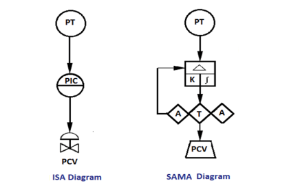
- PID: Refers to a control algorithm that takes a Process Variable (PV), compares it to a Setpoint (SP), and generates a Control Variable (CV) that automatically reacts to the error as PV deviates from SP. If SP = PV, then the CV remains where it is. If the PV increases above the SP, then the CV falls if the PID is configured as direct-acting; or it rises if the PID is configured as reverse-acting.
- Offset: The percentage-of-scale error between a stable output value and its desired value. Offset is usually measured during control loop tuning, and can sometimes be reduced by incrementing the integral aspect of the PID equation.
- Rangeability (turndown): The ratio of an instruments maximum range to its minimum range. If an instruments output signal will remain linear for input ranges that are between 050 and 0100 psig, then its rangeability ratio is 100:50, or 2:1.
- Repeatability: The capacity of an instrument to report the same output value each time a specific input value is detected over a short time span.
- Resolution: The degree to which a change in an instruments input can be If the sensing element of a load cell can only detect weight changes in 0.1 lb increments, then its resolution is 1.6 ounces. A computers resolution is defined by the size of the data word that can be accommodated. A PLCs analog input might have 12-bit resolution, which equates to 4096 discrete values that can be used to represent an input voltage or current. For example, if an input signals range is 010 VDC, a change of 10 V/4096 =.00244 V will be detected.
- Response Time: A measure of the amount of time it takes an output to respond to a given shift in input value.
- Scale: The portion of an instruments design range for which it is calibrated to provide a full scale linear output. It is the calibrated range of the instrument. An instruments scalability is the ratio by which the scale can be different from the range.
- Set point: The point at which a process is supposed to operate (control set point), or the point at which an alarm should occur (alarm set point).
- Span: See Design Range.
- Transducer: To transducer is to convert from one type of energy to another. A relay is a transducer, converting electrical energy to mechanical, as the coil magnetizes and closes its contacts. A pressure transducer converts pressure, as measured mechanically, to electrical energy. An I/P transducer converts electric current to a pneumatic pressure.
- Turndown: See Rangeability.
- Units, Engineering: Units of measure useful to the operator. Examples of engineering units are pounds per hour, feet per second, and degrees Fahrenheit.
- Units, Raw: Units of measure at the transmitter. Examples of raw units are millivolts (mV) and milliamps (mA). These values are generally of little direct use to the operator since they are difficult to interpret until converted into engineering units.
- Process Variable (PV): A process variable is the measured value fed to a control equation, like a PID algorithm.
- Controlled Variable (CV): A control variable is the output of a control equation, like a PID algorithm.