Installations using differential pressure (DP) and in-line pressure transmitters frequently depend on impulse lines to carry pressure from the process penetration points to the transmitter.
Impulse Lines
Impulse lines are used in all types of applications, including where DP measures flow and level. The heat tracing headaches discussed here can emerge anywhere but are particularly problematic for level applications so they are the primary example.
Measuring level in a tank or vessel by using DP is an excellent approach, particularly when there are internal structures or other liquid conditions that make other methods impractical.
Heat Tracing
It has been a favorite approach for countless years, and many plants have an example somewhere. It is usually a simple approach to implement, but challenges can develop in situations where the tank is particularly tall, the process media is often at a high temperature, or there are ambient temperature changes. These conditions create obstacles to effective level readings, made worse by maintenance headaches.
While today’s pressure transmitters have a wide range of operating temperatures, some hot processes may exceed what is tolerable. In that case, the transmitter has to be far enough away from the process medium to protect it from the heat.
Usually, this means a remote diaphragm exposed to the high temperature and sending pressure via a sealed, fluid-filled capillary designed to withstand the heat. Over the length of the impulse line or capillary, cooling should protect the transmitter.
This is fine as far as it goes, but real-world users sometimes encounter implementation problems. If the environment is cold, even only intermittently, the impulse line may cool too much, which causes the high-temperature fill fluid to become excessively viscous at the transmitter end and interferes with accurate pressure transmission.
Careful design can mitigate this heat loss and minimize the problem for the high-pressure side connection at the tank bottom, but the low-pressure side impulse line coming down from the top of the tank has the same problem and is far more difficult to control.
Conventional wisdom says a solution for both sides is simple: wrap all the impulse lines in steam- or electrically-heated tape and the problem is solved.
This may work, but heat tracing is a costly and maintenance-intensive solution with a poor track record for reliability.
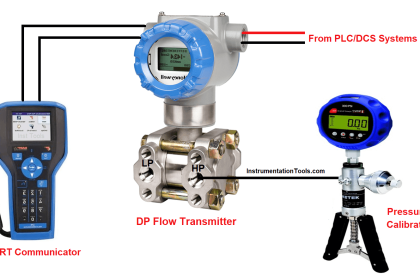
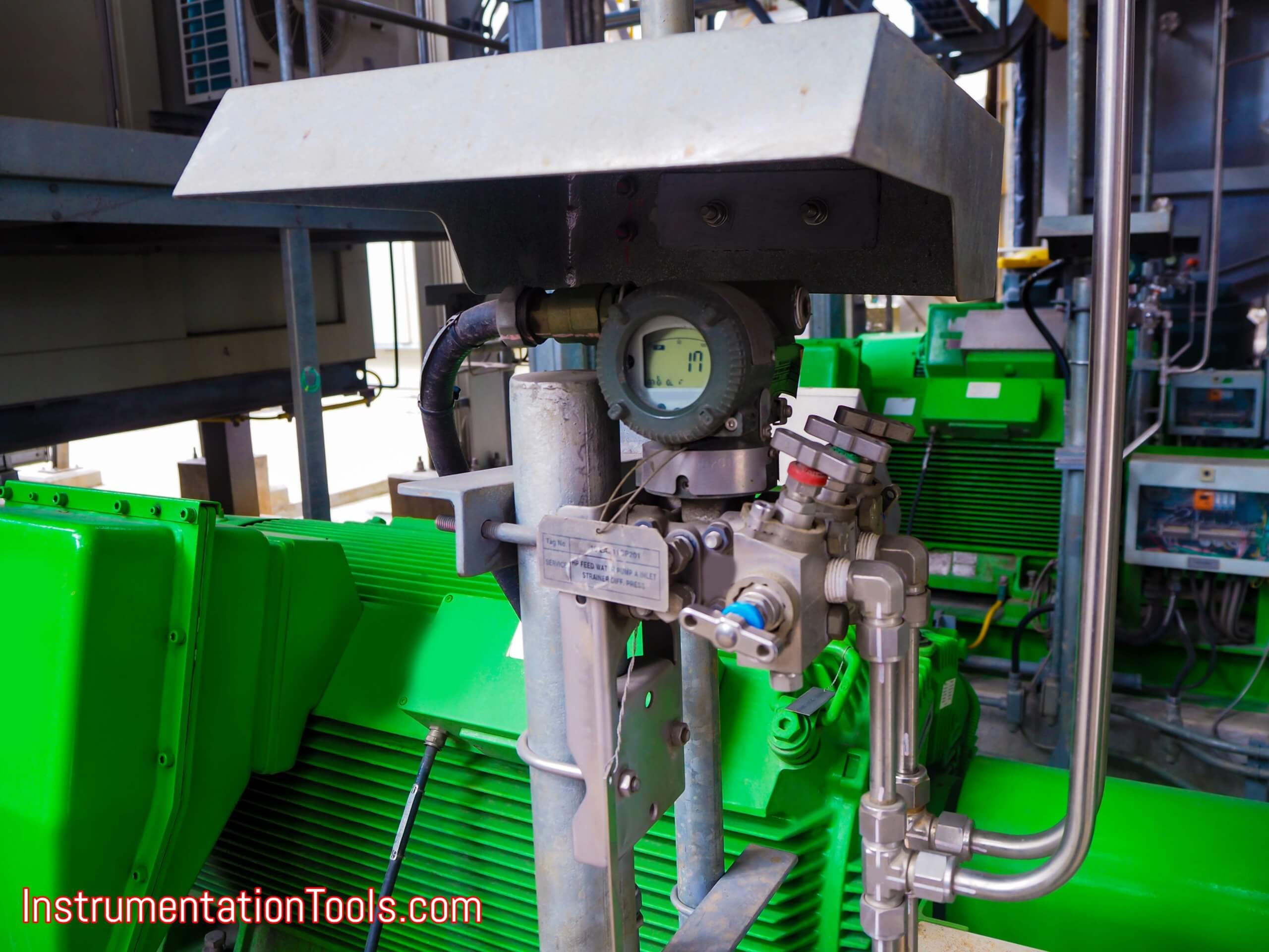
DP Transmitter
Let’s look at this challenge more closely and consider approaches for the high and low-sides individually.
The high side impulse line, which bears the liquid’s weight and temperature, is usually relatively short and close to the tank.
Nonetheless, if the impulse line is configured to provide adequate heat dissipation under normal operating conditions, a particularly cold snap may create a problem.
A better solution than heat tracing is using a Thermal Range Expander, a sealed impulse line arrangement with two sections, each using a different fill fluid.
Building in Heat Tolerance
The Thermal Range Expander may be used at process temperatures up to 770 °F (410 °C) and ambient temperatures as low as -157 °F (-105 °C). It uses a combination of two fill fluids separated from each other with an internal diaphragm.
The hot end connects directly to the process using a flange mount which can bolt to a nozzle on the vessel. Behind the hot-side diaphragm is a small diameter tube filled with high-temperature fluid which transmits pressure to the intermediate diaphragm, which conveys pressure to a second tube filled with a low-temperature fluid. The pressure in the second tube is then measured by the transmitter.
The fill fluid adjacent to the diaphragm adjoining the process is selected to respond quickly at high temperatures, and its temperature and correct viscosity are maintained by the process itself.
The fill fluid in the second tube is selected to respond quickly over the anticipated range of ambient atmospheric temperatures, from cold to hot. In this way, measurement fluctuations due to fill-fluid viscosity issues are eliminated.
Losing Long Lines
Solving the impulse line to the top of the tank can be more of a problem due to its length. Where temperatures are high enough the Thermal Range Expander may be necessary on the top of the tank as well as the bottom.
As with the bottom, there is the temperature stratification concern, but also the pressure created by the fill fluid itself. A better approach eliminates the long impulse line entirely.
An alternative method uses a second transmitter at the vessel top. This transmitter measures the headspace pressure and sends the measurement electronically to the primary transmitter at the bottom. One or both transmitters can be outfit with the Thermal Range Expander if necessary.
This two transmitter system eliminates any need for the long impulse line, along with associated heat tracing or required maintenance, to ensure an accurate reading from the top of the tank. With an electronic connection, there is no reason to doubt the head-space pressure value.
The combination of Thermal Range Expander and remote transmitter System can easily deliver major installation and operational cost-savings as compared to heat-traced exterior units during setup and installation, plus with no electricity or steam needed for heat tracing, the ongoing saving of operating and maintenance costs are also possible.
The Thermal Range Expander reliably reports DP level in the unit in less than one second and is unaffected by ambient temperature changes outside the tower.
This system can also provide an independent pressure reading from the top of the tank. All data is sent from the transmitter at the bottom of the tank, so only one connection to the host system is required.
This technology upgrade can improve process monitoring and reporting over older methods, improve safety by enabling faster response to the development of upset conditions, and saves money.
Interest to add any further points? Share with us through below comments section.
If you liked this article, then please subscribe to our YouTube Channel for Instrumentation, Electrical, PLC, and SCADA video tutorials.
You can also follow us on Facebook and Twitter to receive daily updates.
Read Next:
- Electrical Ground Loops
- Purging of Instruments
- Purged Impulse Lines
- Impulse Steam Traps
- Impulse Piping Installation