In the previous article, we learned about the different I&C engineer roles and responsibilities and the main relevant documents, while some major points can be described below approaches.
Instrumentation and Control (I&C) systems are integral to the operation of many industrial processes, including power generation, oil and gas production, manufacturing, and more. During the Detail Design phase of a project, a lot of focus is given to the I&C systems to ensure their efficient and safe operation.
Instrumentation Engineer Activities
Instrumentation Design Engineers play a crucial role in designing, implementing, and maintaining instrumentation and control systems in a variety of industries.
Here’s a general view of instrument engineers’ typical activities:
- System Design: This involves designing the complete instrumentation system for a project. This includes the selection of appropriate instruments, defining their locations, identifying the connection details, etc.
- Instrument Selection: The engineer selects the appropriate instruments based on process parameters, system requirements, and industry standards. These can include sensors, transmitters, control valves, switches, etc.
- Preparation of Specifications: Engineers prepare detailed technical specifications for each instrument. This includes technical details, operational conditions, maintenance requirements, etc.
- Creation of Design Documents: These can include P&ID (Piping and Instrumentation Diagrams), loop diagrams, instrument data sheets, wiring diagrams, installation details, etc.
- Interface with Other Disciplines: Engineers need to coordinate with other disciplines like process, mechanical, electrical, etc., to ensure that the design is integrated and conflicts are resolved.
- Hazard Analysis: They may be involved in HAZOP (Hazard and Operability) studies to identify potential safety and operational issues.
- Vendor Coordination: This involves coordinating with instrument vendors to ensure that the instruments meet the specifications. It may also include activities like attending FATs (Factory Acceptance Tests).
- Supporting Procurement: Engineers assist procurement teams in the ordering process. This can involve activities like technical bid analysis.
- Testing and Commissioning Support: Engineers provide support during system testing, commissioning, and startup. They may also be involved in resolving any issues that arise during these stages.
- Providing Training: Instrumentation Design Engineers may provide training to the operation and maintenance staff to help them understand how the instrumentation system operates and how to maintain it.
- Continuous Improvement: They monitor the performance of the instrumentation system and suggest improvements. They also stay up-to-date with the latest technology trends and industry standards.
These activities can vary depending on the industry, the specific project requirements, and the organization’s structure and processes.
Instrumentation Engineer Documents
An Instrumentation Design Engineer is responsible for creating, reviewing, and managing several important documents throughout the project lifecycle. These instrument documents serve as technical guidelines, project records, and communication tools.
Below are some key documents typically prepared by an Instrumentation Design Engineer:
- Instrument Data Sheets: These documents provide detailed specifications for each instrument, including its type, size, range, accuracy, material of construction, manufacturer details, etc.
- Piping and Instrumentation Diagrams (P&IDs): These diagrams depict the process flow and show the detailed instrumentation control scheme.
- Instrument Index: An instrument index lists all the instruments involved in the project, along with their key details like tag number, type, location, function, etc.
- Loop Diagrams: These diagrams show the detailed wiring connections between field instruments, junction boxes, marshalling cabinets, and system cabinets.
- Instrument Location Layouts: These layouts show the physical location of the instruments in the plant, aiding in installation and maintenance.
- Hook-up Diagrams: The hook-up diagrams depict the detailed installation process for each instrument, including all the necessary accessories.
- Bill of Materials (BOM): This includes a list of all instruments and accessories required for the project.
- Cable Schedules: These provide details about the type, size, length, and route of the cables used for each instrument.
- Functional Design Specifications (FDS): These define the expected performance and functional requirements of a control system.
- Cause and Effect Matrix: This document outlines how the control system should react to each possible input signal, effectively depicting the control philosophy of the system.
- Factory Acceptance Test (FAT) and Site Acceptance Test (SAT) Procedures: These provide detailed procedures for testing the systems at the vendor’s and the customer’s site, respectively.
- Standard Operating Procedures (SOPs) and Maintenance Manuals: These are prepared to provide guidance to operators and maintenance personnel.
- Hazard and Operability Study (HAZOP) Reports: These reports identify potential safety and operational issues.
The type and detail of these documents can vary based on the specific project requirements and industry standards.
Instrumentation During the Detail Design Phase
Below is a general view of I&C engineer activities and documents during the Detail Design phase:
1) Input Analysis
As the first step of doing a process project during Detail Design, some data shall be gathered and analyzed for finding the project requirements, limitations, and considerations.
Normally these inputs include (Technical) Contract (as a basis for defining the scope of work and supply and following responsibilities, further to defined Customer/ User Requirements), Design Basis (Documents and data provided by licensor or Basic Design Contractor), Business Requirements (based on commercial items/limitations of contract and customer approach on supplying of budgets), Approved Vendor Lists (and available technologies), Standards/ Codes/ Governmental or Local Rules.
Further to these inputs, all stockholder’s concerns and also company procedures/ practices are the main inputs of doing the first step of (I&C) detail design.
2) Preparing Specifications and Datasheets
By studying the mentioned inputs further to some activities (including participation in meetings, conversations/discussions with other technical disciplines, and doing some calculations) I&C specialists shall prepare required project specifications, data sheets, and requirements for some following required documents/ materials/ equipment.
The main items in these steps are
- P&ID’s Preparations/ Finalization
- Overall I&C Requirements Concepts (considerations)
- Plant Process Data
- HAZOP/SIL Studies & Safety Requirements
- Hazardous Area Classification
- Plant Layout/ Project Area (Boundaries/ Limitations/ Locations), and also
- Power/ Utility Requirements.
3) Preparing Documents for Procurement/ Supplying of Materials
I&C Specialists shall prepare all required documents for Procurement / Supplying of Required Instruments, Auxiliary items required for Instrumentation & Signaling (including Cables, Tubes, Fittings, Junction Boxes, Cable Trays, and Ladders, …), required Project Packages/ Equipment (in the scope of other disciplines), and also All required systems and sub-systems (including DCS, ESD, F&G, PLC, …).
Of course, the Procurement phase is very complicated and shall be done based on exact planning and assigning man-hours at suitable times. It shall be mentioned here that some of the items in each project are considered as Long-Delivery items which need more notices and activation at the preliminary times of the project.
4) Reviewing of Vendor Documents
During Purchasing of Packages/ Equipment/ Instruments /Auxiliary Items, relevant vendors shall submit required documents that are monitored and studied by I&C specialists for any probable comments or approvals (via comparison with project requirements).
Proceeding with each purchase requestion /order will be done by company procedures in different ways and via project planning and in some cases, it may include other probable activities (for example actual tests).
5) Preparing Documents for Site Construction & Equipment Installations
Of course, some I&C documents are needed during Site Construction & Equipment Installations, and such items are prepared during the project progress and planned schedule.
In fact, such documents shall be ready at suitable times, and any fault or disturbance on such documents may hold the site activities.
6) Core Activities
Some of the I&C activities and documents can be mentioned as core items due to their importance and extensive action domains.
I&C Project database (Instrument Index) and implementing project safety requirements, further to the overall control system block diagram(philosophy) are some examples that have relations to approximately all I&C activities/ documents (or domains).
7) Different Size of Scope based on Project Execution Types
Based on different applicable contracts between the client and Detail Engineering company the size and some types of activities of I&C scope can be changed. As an example, the mentioned scope may be found differently if the project is EPC, EPS, Turn-Key, or other possible cases.
One of the major changes in different project types can be seen in engaging I&C specialists (from Detail Engineering Company) in Commissioning & Start-Up phase.
I&C Engineer Activities on Systems & Sub-Systems
If we make focus on the title of I&C, we can find two main goals as Instrumentation and Control. In the Instrumentation part of activities, the relevant specialists shall provide all suitable instruments with all related site installation considerations, while in the part of Control, they shall follow suitable systems (including Hardware & Software) for best performance operations and all required Interlocks and Safety Logics.
Already we have mentioned that one of the core activities set of I&C specialists is related to project requirements on the subject of Systems and Sub-Systems. In such activities and documents, I&C specialists shall provide suitable systems with all documents to satisfy the project requirements on functions and communication links.
For implementing such targets, I&C design engineers shall follow the sequences shown in Figure-1 to provide some documents by themselves to help the system vendors in order to provide the correct documentation.
In fact, the I&C specialists have vital roles to guide the system vendors on configuring the best arrangement for project requirements in compliance with other systems and control & safety functions considered in the project control philosophy.
Just to show such complexity, it should be mentioned that the brands and models of different systems and sub-systems are not the same, and in spite of the sizes and their capabilities, all shall follow the same harmony in the whole project control philosophy.
However, the documentation produced by the system vendor shall have the same frames, formats, and assignments as other project documentation and I&C specialists have a serious role in such target.
Figure -2 shows one model on the main sequences of provision of required documents by the system vendor. By reviewing this model, it may be clear that the provision of documents shall follow the logical routes at the right times, and in some feedback routes the documents need new revision to satisfy some items.
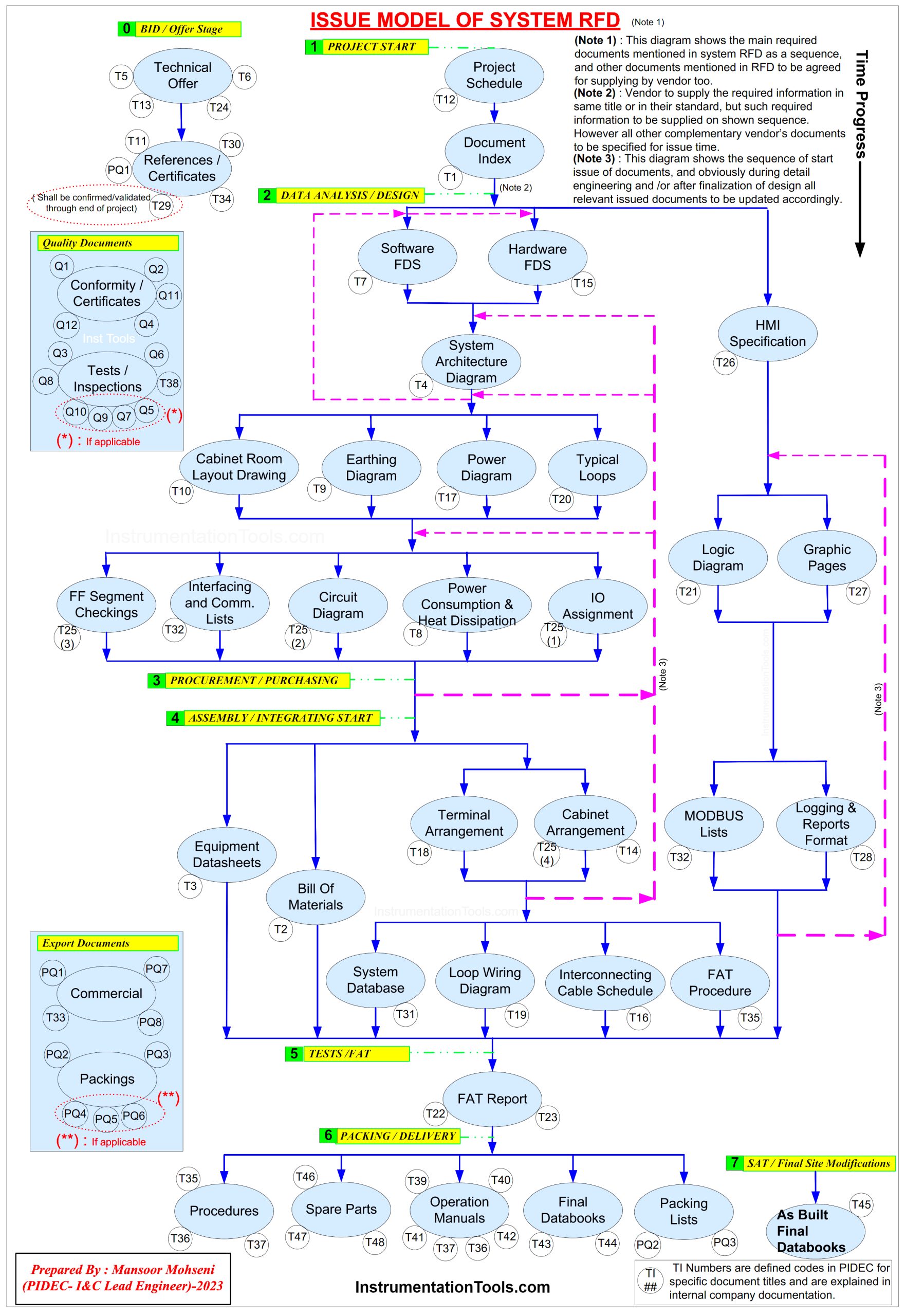
Figure-2: Issue Model of System RFD (Required For Documents)
Figure-2 also shows different required information and data which shall appear in different document titles. Such settings normally are done during a kick-off meeting in which all participants make agreements for the production of different document titles (which are usually known as VDIS).
As it is clear in the model, the Detail Design company may inform the system vendor of project requirements by some predefined codes and finally, they agreed to the inclusion of codes in each document title.
I&C Engineer Activities on Purchasing
Some I&C engineer activities and documents are related to Purchasing sequences which are used for Instruments, Systems, and Packages (Equipment) in approximately similar ways.
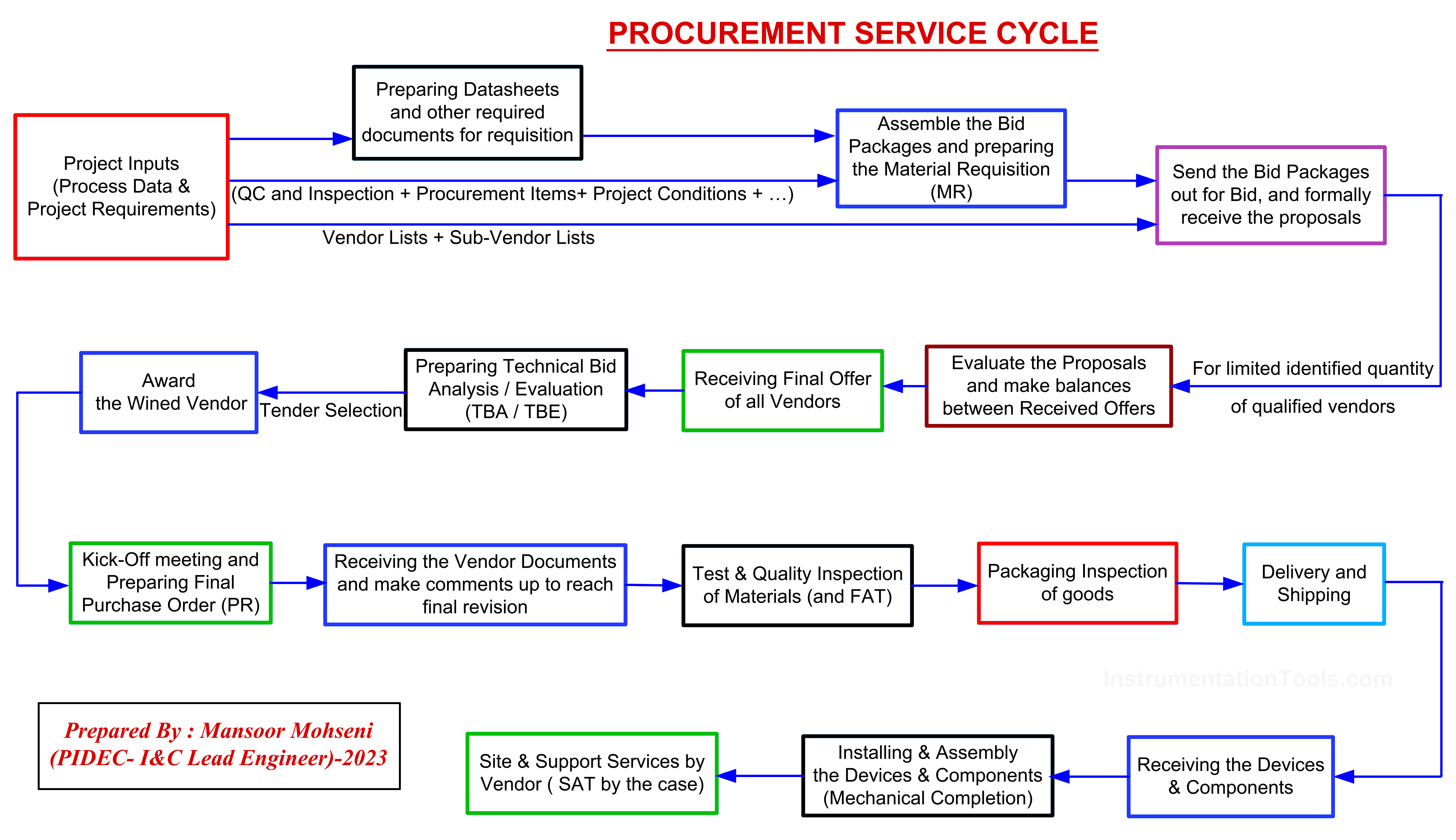
Figure-3: Procurement Service Cycle
Figure-3 shows a model of Purchasing Sequence and by studying it the role of specialists in the preparation of initial documents and following activities for vendor document checking and approval of made items are clear.
Instrumentation Detail Design Phase:





Wow, this article is a goldmine of information for Instrumentation Engineers during the Detail Design phase! It reminds me of my Honeywell days! It covers key activities and essential documents that are crucial for project execution. A must-read for engineers looking to enhance their skillset. Thanks for sharing! 👍
Amazing stuff, never see anything similar, thank you very much for sharing that precious material with us.