Both Transmitter and Transducer are devices, which convert one form of energy into another form and give an output signal.
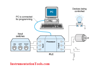
The output signal is connected to any device like indicator, controller in control panel, DCS, and PLC systems. These systems interpret the measured parameters and display the equivalent readings to the operators and record the readings.
However, there are some differences that depend upon applications at the receiving end. The receiving devices include a control panel, digital indicators, DCS, programmable controllers (PLC), or panel chart recorders.
The words Transducer, and transmitter are used interchangeably across the instrumentation industry today.
For example, some of the manufacturers of miniature pressure instruments called them as pressure transmitters, and few manufacturers mention it as a pressure transducer.
But the words transducer and transmitter actually have fundamentally different meanings.
The determining factors while selecting the right transducer or transmitter for an application are accuracy, range, and scalability.
There are a wide variety of pressure transmitters and transducers for various applications like process industrial automation, aerospace, automotive, and refrigeration systems.
Transmitter versus Transducer
The difference between the transmitter and transducer is discussed below.
Function
Function of a transducer
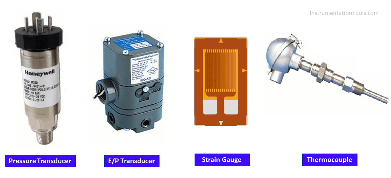
The transducer detects and senses the presence, magnitude, and physical priority being measured. It provides a proportional electrical signal.
Examples: Strain gauge, load cell, LVDT, RVDT, Thermocouple, etc.
Transducer has two elements
- Sensing element
- Transduction element.
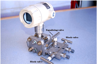
A pressure transducer is an electromechanical device for measuring the process pressure value into an equivalent voltage.
Function of a Pressure transmitter
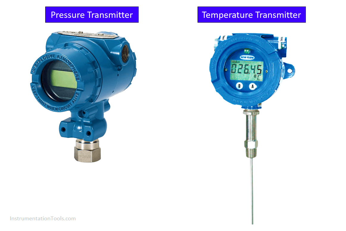
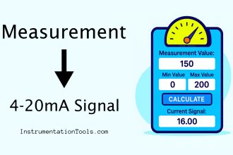
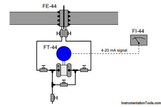
On the other hand, transmitters measures process pressure value into equivalent current generally in the range 4-20 mA.
In general, transmitters are preferred when sending a signal over hundreds of meters. These devices are exclusively for measuring process parameters and communicating the output electronically or visually in industries.
Signal
The transducer sends a signal in milli-volts (mV) or Volts (V) or any other forms.
Transmitter sends signals in standard 4 to 20 milliamps (mA).
For example, pressure transducers are devices that convert the applied pressure by mechanical force into electrical energy, it becomes a signal output that is linear and proportional to the applied pressure.
If the electrical connections in a process application are short, such as application in the laboratory or inside an electronic enclosure, a pressure transducer is more needed. The output is in the form of equivalent voltage (other forms also available depends on the type of device).
The thermocouple is a temperature transducer, its output in typical mV signal that do not have linear temperature characterization. If we use a thermocouple without an additional circuit is called a transducer because it converts heat (temperature) energy into electrical energy (mV).
The temperature transmitter sends the output in a 4-20 mA signal. A current signal is more resistant to interference and noise than a voltage signal.
In case of transmitter signals – On-board electronics capable of operating with maximum current usage of less than 4 mA.
Power Consumption
Typically transducers have lower operating power, less power consumption requirements than a transmitter.
On the other hand, Transmitters consume more power during operation.
Advanced Features
A smart Transmitter sends an output 4 to 20 mA signal with an additional digital superimposed signal (whenever required) which allows a user to collect more information and other device variables besides process variables.
Transmitter has additional electronic circuitry that linearizes, compensates, and amplifies the signal from a sensor or transducer. Different signal types are typically voltage signals, milli-amp, resistance, or digital. The instrument can transmit the signal to a remote receiver.
Transmitters can be equipped with a local display unit.
In the measurement of some process parameters say pressure, Transmitters and transducers are virtually meet simple measurement requirements, the main difference being the kind of electric signal each sends.
Many transmitters offer a variety of calibration options including turndown and zero & span adjustment. Smart transmitter’s health status can be checked, calibrated, tested, and reset remotely using a bus network.
The transducer’s health status cannot be checked remotely. There won’t be a display to read the readings.
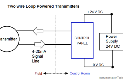
Most transmitters are current-output devices and may have two or more wire configurations. Significant cost savings can be made in the case of a two-wire configuration, in which power and signal are carried on the same two wires.
Digital output transmitters normally consist of a microprocessor that converts measured process parameters into digital code which are transmitted to a remote receiver or host via wires, optical fibers, or radio. There is a number of protocols available to communicate with a host. Foundation field bus, HART, Profibus are few to mention.
Transducers don’t have such advanced options.
Beyond sending process parameter values, digital transmission can include diagnostic information, status, and alarms and can also facilitate remote configuration of transmitters.
Transducers don’t have advanced features, no configurable options, they are not scalable.
Interference
Transmitter outputs are less susceptible to electromagnetic interference than voltage output transducers.
Transducers are used with simple signal conditioning, more sensitive to electromagnetic interference. If the cables are long, the connecting cables may cause significant errors.
If you liked this article, then please subscribe to our YouTube Channel for Instrumentation, Electrical, PLC, and SCADA video tutorials.
You can also follow us on Facebook and Twitter to receive daily updates.
Read Next:


A very good explained in your description, all points are include.