UPS should be designed and constructed in accordance with IEC 62040. All the components should be mounted in an indoor, floor-mounted, metal enclosed panel with enclosure protection IP 42.
UPS Cubicle must be dust and vermin-proof and designed for ambient of 50º C and relative humidity band as per site condition.
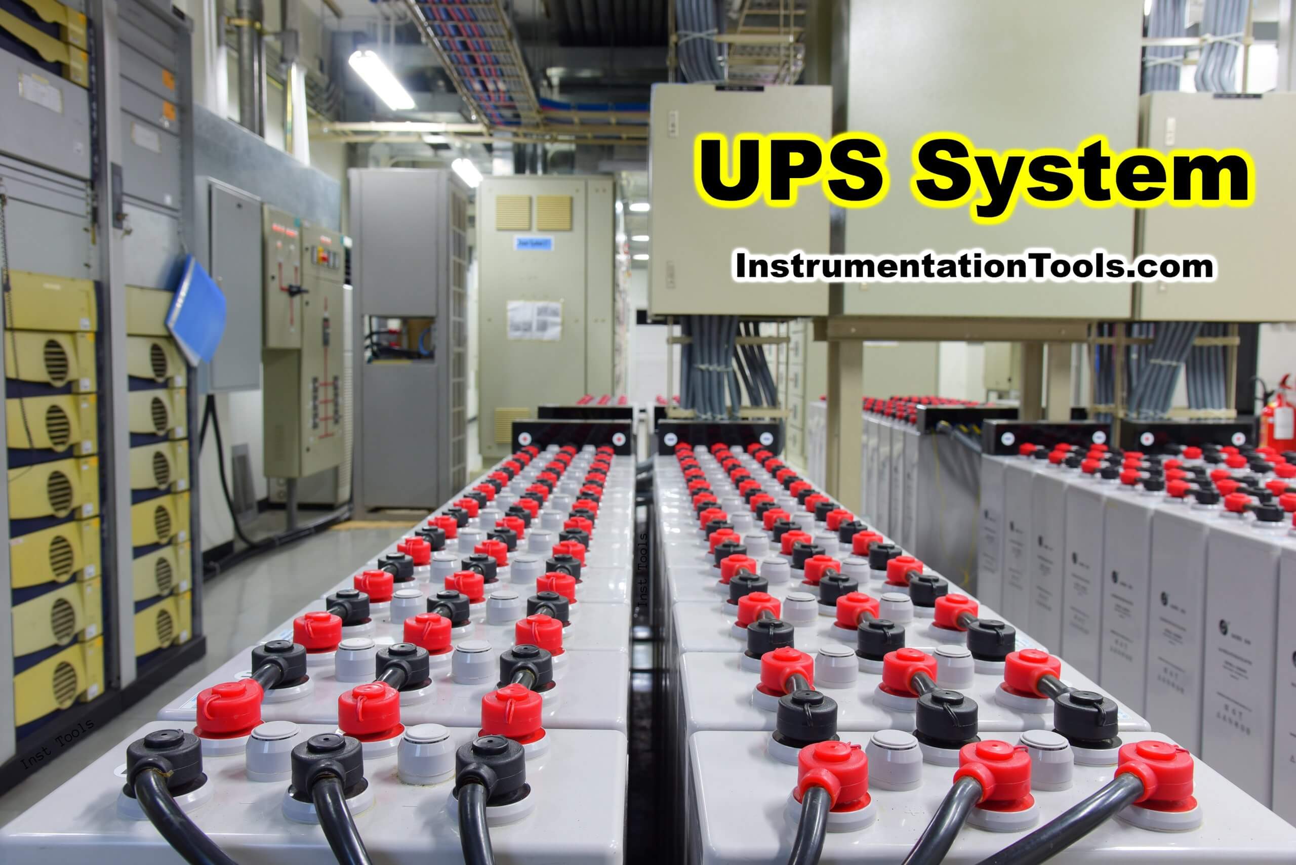
Technical Specification for Uninterrupted Power Supply (UPS)
The UPS system shall consist of
- Incoming MCCB in Inverter lines & By-pass lines
- Input Isolation Transformer
- Harmonic Filter
- Rectifier / charger unit
- Lead Acid sealed maintenance free Batteries
- Inverter unit
- Servo-controlled Voltage Regulator in the Bypass line
- Automatic switching (Static Switch)
- Maintenance bypass switch
- Protective devices and other accessories
- Control and Display Unit for monitoring of parameters and control of UPS
The solid-state rectifier/charger shall convert incoming AC power to DC power. The rectifier/charger output shall be fed to a solid-state inverter.
The inverter shall convert the DC power into AC power which shall supply to the load. Upon failure of AC power or in case voltage drops below the operating range of battery charger, input power for inverter shall automatically be supplied from the battery with no interruption/disturbance in inverter output in excess of limits specified in this specification. At the same time, UPS shall energize an alarm circuit.
UPS shall have a storage battery with 30 min + 30 min (for double battery bank) minimum backup capacity to meet the power requirements in the event of failure of the main supply. Battery Bank shall consist of 12 Volt battery blocks.
When A/C power is restored, the input power for the inverter and for recharging the battery shall automatically be supplied from rectifier/charger output without interruption/ disturbance in inverter output in excess of the limits specified herein (in these specifications).
If the battery is exhausted before AC power is restored, the UPS shall shut down automatically.
System Configuration
A parallel Redundant UPS system shall comprise two sets of UPS streams each of a designed kVA rating and a common Bypass with servo controlled Voltage Stabilizer (SCVS).
Each UPS shall be supplied with Battery banks of a size suitable for UPS rating. Both the UPS shall run in parallel and share the connected load.
The switchover from UPS to standby and vice versa shall be without any interruption. Bypass with SCVS shall come in line only when both the UPS are out of order and not in working condition.
Rectifier / Charger Unit
An input AC filter shall be incorporated into the rectifier or charger unit. The filter is not to be an add-on in front of the rectifier or charger.
This filter’s purpose is to reduce the current harmonics feedback into the input AC line to not more than 5%. The filter is needed also to improve the input power factor so that it is 0.8 lag or better.
The rectifier/charger unit shall be provided with the feature which does not allow input power required to go beyond 20% of the rated load upon resumption of AC power after operation of UPS on batteries.
Power semiconductors in the rectifier/charger shall be used with fast-acting fuses so that the loss of any one power semiconductor will not cause cascading failures.
All fuses shall be provided with a blown fuse indicator with an alarm indicator on the control panel. The filter shall be adequate to ensure that the DC output of the rectifier/ charger will meet the input requirements of the inverter.
Inverter Unit
The inverter unit shall be an IGBT based capable of accepting the output of the rectifier and charger or the unregulated voltage of the battery and provide regulated rated AC output within specified limits. Means shall be provided to hold the inverter output frequency to +0.1% for both steady state and transient conditions.
Total frequency deviation, including short time fluctuations and drift, shall not exceed +0.1% from the rated frequency. The inverter output shall stay synchronized with the static bypass line provided the static bypass line remains within +3 Hz of the nominal frequency.
If the line frequency goes outside these limits, the inverter is to break synchronization with the line and run on its internal frequency. When the line frequency returns, within limits, the inverter output is to automatically re-synchronize with the line.
The rate of change of frequency is not to exceed 0.1 Hz per second. The unit shall be provided with an internal switch so that the synchronizing frequency range can be changed from +3 Hz to +1 Hz or to +0.5 Hz.
Static Transfer Switch
The Static Transfer Switch, using solid state devices, shall be provided to transfer the load between the UPS module and the static bypass line uninterrupted.
Automatic static load transfers shall be initiated when a system overload is greater than specified here, a branch load circuit faults, or a fault within the UPS module occurs.
If the static transfer was caused by an overload or branch fault and this condition was rectified, then the static transfer switch is to automatically re-transfer the load to the UPS module.
The static transfer switch shall be sized to provide 125% rated load continuously. The switch shall also have an overload rating of 2000 % rated load for two cycles.
Maintenance Bypasses Switch
A manually operated maintenance bypass switch is to be incorporated into the UPS module cabinet that will connect the load to the input AC power source bypassing the rectifier/charger, inverter, and static transfer switch.
While the load is on the maintenance bypass line, it shall be possible to check out the operation of the rectifier/charger, inverter, and static transfer switch. It shall also be possible to check the battery operation.
Control and Display Unit
The control Panel is to depict a single-line diagram of the UPS. Indicating Lights shall be integrated with the single-line diagram to illustrate the status of the UPS power paths.
The functions whose status is to be displayed shall include, but are not limited to the following:
- Input power available
- Output power available
- Normal operation
- Bypass operation
In addition to the above, each UPS shall be supplied with LED/LCD control and Display Unit to monitor various parameters as explained in various sub-clauses of this section and others as deemed necessary by the Manufacturer.


Please tell me UPS calculation (1 Kvar,2 Kvar ,3 Kvar.5 Kvar )How many Batteries Required 12 v Batteries. and Output Power 230 VAC. Back Up 2 to 3 Hours.