A through knowledge of the information presented in the title block, the revision block, the notes and legend, and the drawing grid is necessary before a drawing can be read. This information is displayed in the areas surrounding the graphic portion of the drawing.
The ability to read and understand information contained on drawings is essential to perform most engineering-related jobs. Engineering drawings are the industry’s means of communicating detailed and accurate information on how to fabricate, assemble, troubleshoot, repair, and operate a piece of equipment or a system.
To understand how to “read” a drawing it is necessary to be familiar with the standard conventions, rules, and basic symbols used on the various types of drawings. But before learning how to read the actual “drawing,” an understanding of the information contained in the various non-drawing areas of a print is also necessary.
This article will address the information most commonly seen in the non-drawing areas of engineering drawings. Because of the extreme variation in format, location of information, and types of information presented on drawings from vendor to vendor and site to site, all drawings will not necessarily contain the following information or format, but will usually be similar in nature.
In this article the terms print, drawing, and diagram are used interchangeably to denote the complete drawing. This includes the graphic portion, the title block, the grid system, the revision block, and the notes and legend. When the words print, drawing, or diagram, appear in quotes, the word is referring only to the actual graphic portion of the drawing.
Anatomy of a Drawing
A generic engineering drawing can be divided into the following five major areas or parts.
- Title block
- Grid system
- Revision block
- Notes and legends
- Engineering drawing (graphic portion)
The information contained in the drawing itself will be covered in subsequent modules. This module will cover the non-drawing portions of a print. The first four parts listed above provide important information about the actual drawing. The ability to understand the information contained in these areas is as important as being able to read the drawing itself. Failure to understand these areas can result in improper use or the misinterpretation of the drawing.
The Title Block
The title block of a drawing, usually located on the bottom or lower right hand corner, contains all the information necessary to identify the drawing and to verify its validity. A title block is divided into several areas as illustrated by Figure 1.
First Area of the Title Block
The first area of the title block contains the drawing title, the drawing number, and lists the location, the site, or the vendor. The drawing title and the drawing number are used for identification and filing purposes. Usually the number is unique to the drawing and is comprised of a code that contains information about the drawing such as the site, system, and type of drawing.
The drawing number may also contain information such as the sheet number, if the drawing is part of a series, or it may contain the revision level. Drawings are usually filed by their drawing number because the drawing title may be common to several prints or series of prints.
Second Area of the Title Block
The second area of the title block contains the signatures and approval dates, which provide information as to when and by whom the component/system was designed and when and by whom the drawing was drafted and verified for final approval.
This information can be invaluable in locating further data on the system/component design or operation. These names can also help in the resolution of a discrepancy between the drawing and another source of information.
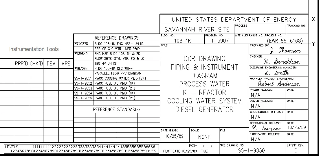
Figure 1 : Title Block
Third Area of the Title Block
The third area of the title block is the reference block. The reference block lists other drawings that are related to the system/component, or it can list all the other drawings that are cross-referenced on the drawing, depending on the site’s or vendor’s conventions. The reference block can be extremely helpful in tracing down additional information on the system or component.
Other information may also be contained in the title block and will vary from site to site and vendor to vendor. Some examples are contract numbers and drawing scale.
Drawing Scale
All drawings can be classified as either drawings with scale or those not drawn to scale. Drawings without a scale usually are intended to present only functional information about the component or system. Prints drawn to scale allow the figures to be rendered accurately and precisely. Scale drawings also allow components and systems that are too large to be drawn full size to be drawn in a more convenient and easy to read size. The opposite is also true. A very small component can be scaled up, or enlarged, so that its details can be seen when drawn on paper.
Scale drawings usually present the information used to fabricate or construct a component or system. If a drawing is drawn to scale, it can be used to obtain information such as physical dimensions, tolerances, and materials that allows the fabrication or construction of the component or system.
Every dimension of a component or system does not have to be stated in writing on the drawing because the user can actually measure the distance (e.g., the length of a part) from the drawing and divide or multiply by the stated scale to obtain the correct measurements.
The scale of a drawing is usually presented as a ratio and is read as illustrated in the following examples.
1″ = 1″ : Read as 1 inch (on the drawing) equals 1 inch (on the actual component or system). This can also be stated as FULL SIZE in the scale block of the drawing. The measured distance on the drawing is the actual distance or size of the component.
3/8″ = 1′ : Read as 3/8 inch (on the drawing) equals 1 foot (on the actual component or system). This is called 3/8 scale. For example, if a component part measures 6/8 inch on the drawing, the actual component measures 2 feet.
1/2″ = 1′ : Read as 1/2 inch (on the drawing) equals 1 foot (on the actual component or system). This is called 1/2 scale. For example, if a component part measures 1-1/2 inches on the drawing the actual component measures 3 feet.
Grid System
Because drawings tend to be large and complex, finding a specific point or piece of equipment on a drawing can be quite difficult. This is especially true when one wire or pipe run is continued on a second drawing. To help locate a specific point on a referenced print, most drawings, especially Piping and Instrument Drawings (P&ID) and electrical schematic drawings, have a grid system.
The grid can consist of letters, numbers, or both that run horizontally and vertically around the drawing as illustrated on Figure 2. Like a city map, the drawing is divided into smaller blocks, each having a unique two letter or number identifier.
For example, when a pipe is continued from one drawing to another, not only is the second drawing referenced on the first drawing, but so are the grid coordinates locating the continued pipe. Therefore the search for the pipe contained in the block is much easier than searching the whole drawing.

Figure 2 : Example of a Grid
Revision Block
As changes to a component or system are made, the drawings depicting the component or system must be redrafted and reissued. When a drawing is first issued, it is called revision zero, and the revision block is empty.
As each revision is made to the drawing, an entry is placed in the revision block. This entry will provide the revision number, a title or summary of the revision, and the date of the revision. The revision number may also appear at the end of the drawing number or in its own separate block, as shown in Figure 2, Figure 3.
As the component or system is modified, and the drawing is updated to reflect the changes, the revision number is increased by one, and the revision number in the revision block is changed to indicate the new revision number.
For example, if a Revision 2 drawing is modified, the new drawing showing the latest modifications will have the same drawing number, but its revision level will be increased to 3. The old Revision 2 drawing will be filed and maintained in the filing system for historical purposes.

Figure 3 : Revision Block
Changes
There are two common methods of indicating where a revision has changed a drawing that contains a system diagram. The first is the cloud method, where each change is enclosed by a hand-drawn cloud shape, as shown in Figure 4.
The second method involves placing a circle (or triangle or other shape) with the revision number next to each effected portion of the drawing, as shown in Figure 4. The cloud method indicates changes from the most recent revision only, whereas the second method indicates all revisions to the drawing because all of the previous revision circles remain on the drawing.

Figure 4 : Methods of Denoting Changes
The revision number and revision block are especially useful in researching the evolution of a specific system or component through the comparison of the various revisions.
Notes and Legend
Drawings are comprised of symbols and lines that represent components or systems. Although a majority of the symbols and lines are self-explanatory or standard (as described in later modules), a few unique symbols and conventions must be explained for each drawing. The notes and legends section of a drawing lists and explains any special symbols and conventions used on the drawing, as illustrated on Figure 5.
Also listed in the notes section is any information the designer or draftsman felt was necessary to correctly use or understand the drawing. Because of the importance of understanding all of the symbols and conventions used on a drawing, the notes and legend section must be reviewed before reading a drawing.

Figure 5 : Notes and Legends


Thanks a lot for helping me on how to read and undestand correctly a drawing.