To read and interpret electrical diagrams and schematics, the basic symbols and conventions used in the drawing must be understood. This article concentrates on how electrical components are represented on diagrams and schematics.
Symbology
To read and interpret electrical diagrams and schematics, the reader must first be well versed in what the many symbols represent. This chapter discusses the common symbols used to depict the many components in electrical systems. Once mastered, this knowledge should enable the reader to successfully understand most electrical diagrams and schematics.
The information that follows provides details on the basic symbols used to represent components in electrical transmission, switching, control, and protection diagrams and schematics.

Figure 1 Basic Transformer Symbols
Transformers
The basic symbols for the various types of transformers are shown in Figure 1 (A). Figure 1 (B) shows how the basic symbol for the transformer is modified to represent specific types and transformer applications.
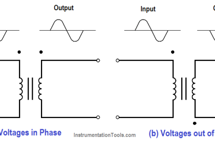
In addition to the transformer symbol itself, polarity marks are sometimes used to indicate current flow in the circuit. This information can be used to determine the phase relationship (polarity) between the input and output terminals of a transformer. The marks usually appear as dots on a transformer symbol, as shown in Figure 2.

Figure 2 Transformer Polarity
On the primary side of the transformer the dot indicates current in; on the secondary side the dot indicates current out.
If at a given instant the current is flowing into the transformer at the dotted end of the primary coil, it will be flowing out of the transformer at the dotted end of the secondary coil. The current flow for a transformer using the dot symbology is illustrated in Figure 2.
Switches
Figure 3 shows the most common types of switches and their symbols. The term “pole,” as used to describe the switches in Figure 3, refers to the number of points at which current can enter a switch.
Single pole and double pole switches are shown, but a switch may have as many poles as it requires to perform its function. The term “throw” used in Figure 3 refers to the number of circuits that each pole of a switch can complete or control.
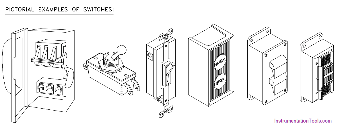
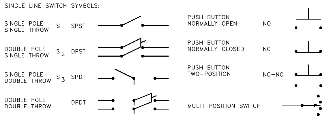
Figure 3 Switches and Switch Symbols
Figure 4 provides the common symbols that are used to denote automatic switches and explains how the symbol indicates switch status or actuation.
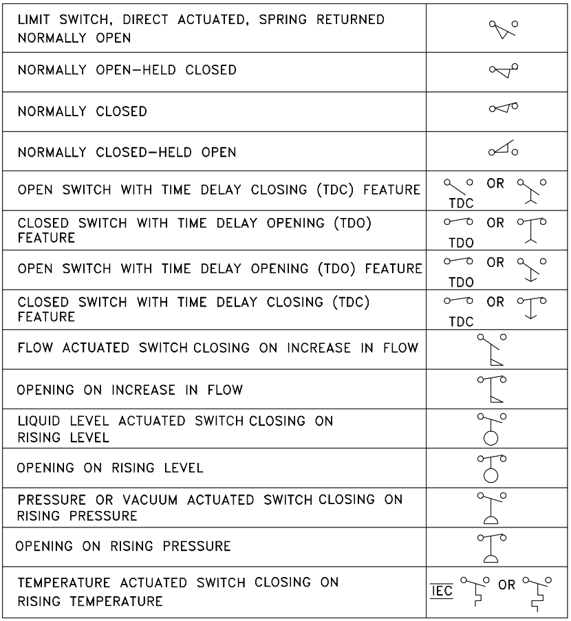
Figure 4 Switch and Switch Status Symbology
Fuses and Breakers
Figure 5 depicts basic fuse and circuit breaker symbols for single-phase applications.
In addition to the graphic symbol, most drawings will also provide the rating of the fuse next to the symbol. The rating is usually in amps.


Figure 5 Fuse and Circuit Breaker Symbols
When fuses, breakers, or switches are used in three-phase systems, the three-phase symbol combines the single-phase symbol in triplicate as shown in Figure 6.
Also shown is the symbol for a removable breaker, which is a standard breaker symbol placed between a set of chevrons. The chevrons represent the point at which the breaker disconnects from the circuit when removed.
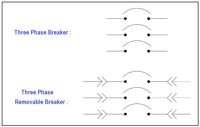
Figure 6 Three-phase and Removable Breaker Symbols
Relays, Contacts, Connectors, Lines, Resistors, and Miscellaneous Electrical Components
Figure 7 shows the common symbols for relays, contacts, connectors, lines, resistors, and other miscellaneous electrical components.

Figure 7 Common Electrical Component Symbols
Large Components
The symbols in Figure 8 are used to identify the larger components that may be found in an electrical diagram or schematic. The detail used for these symbols will vary when used in system diagrams.
Usually the amount of detail will reflect the relative importance of a component to the particular diagram.


Figure 8 Large Common Electrical Components
Types of Electrical Diagrams or Schematics
There are three ways to show electrical circuits. They are wiring, schematic, and pictorial diagrams. The two most commonly used are the wiring diagram and the schematic diagram.
The uses of these two types of diagrams are compared in Table 1.

The pictorial diagram is usually not found in engineering applications for the reasons shown in the following example. Figure 9 provides a simple example of how a schematic diagram compares to a pictorial equivalent.
As can be seen, the pictorial version is not nearly as useful as the schematic, especially if you were trying to obtain enough information to repair a circuit or determine how it operates.

Figure 9 Comparison of an Electrical Schematic and a Pictorial Diagram
Figure 10 provides an example of the relationship between a schematic diagram (Figure 10A) and a wiring diagram (Figure 10B) for an air drying unit. A more complex example, the electrical circuit of an automobile, is shown in wiring diagram format in Figure 11 and in schematic format in Figure 12.
Notice that the wiring diagram (Figure 11), uses both pictorial representations and schematic symbols. The schematic (Figure 12) drops all pictorial representations and depicts the electrical system only in symbols.

Figure 10 Comparison of an Electrical Schematic and a Wiring Diagram

Figure 11 Wiring Diagram of a Car’s Electrical Circuit
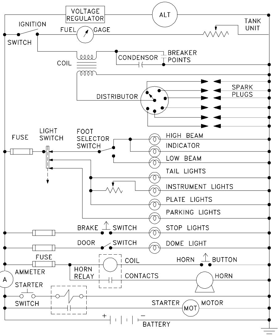
Figure 12 Schematic of a Car’s Electrical Circuit
When dealing with a large power distribution system, a special type of schematic diagram called an electrical single line is used to show all or part of the system. This type of diagram depicts the major power sources, breakers, loads, and protective devices, thereby providing a useful overall view of the flow of power in a large electrical power distribution system.
On power distribution single lines, even if it is a 3-phase system, each load is commonly represented by only a simple circle with a description of the load and its power rating (running power consumption). Unless otherwise stated, the common units are kilowatts (kW). Figure 13 shows a portion of an electrical distribution system at a nuclear power plant.

Figure 13 Example Electrical Single Line