In this article, you will learn the fundamentals using an example of controlling the PLC output using push buttons and solenoid.
Important Note: The PLC logic is prepared for educational purposes and assists students and technicians in learning the fundamentals of PLC.
PLC Output using Push Buttons
Problem Statement
Design a PLC ladder logic for the following application.
We are using two push buttons to control the Solenoid.
When Push Button 1 or Push Button 2 is pressed and then released, then Solenoid will be ON.
When Push Button 1 or Push Button 2 is pressed again and then released, then Solenoid will be OFF.
PLC Learning Video
This video helps you to learn the PLC programming concepts with this example program.
Required Inputs and Outputs
Digital Inputs:
The required DI signals are listed below.
Push Button 1: I0.0
Push Button 2: I0.1
Digital Output:
The required DO signals are listed below.
Solenoid: Q0.0
Ladder Diagram
PLC Program Description
We used Schneider Electric PLC software.
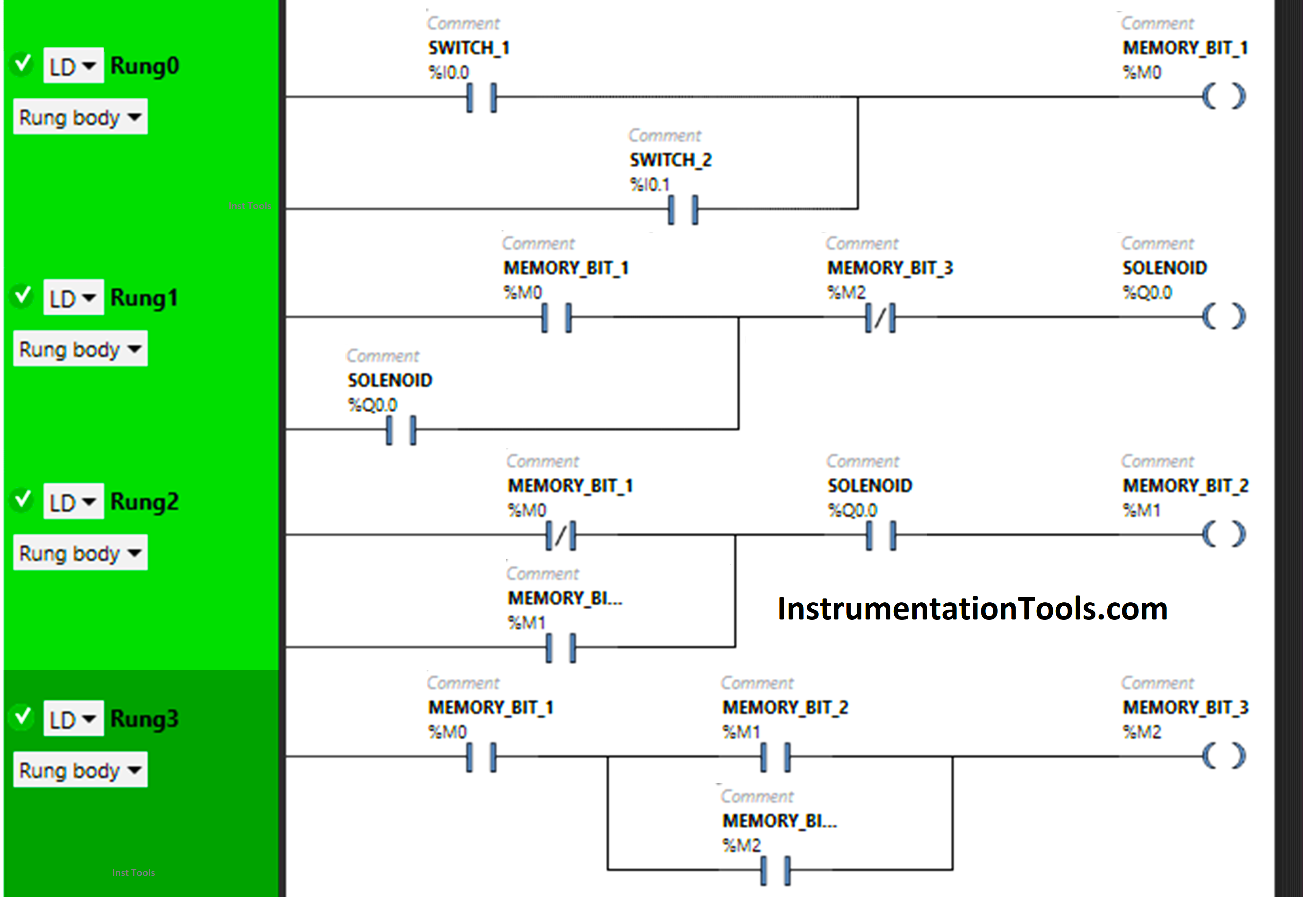
In the above program, we used Normally-Open Contacts as well as Normally-Closed Contact and Memory Bits.
Normally Closed Contact is used for Memory Bit 1 in Rung 2 and Memory Bit 3 in Rung 1.
In Rung 0, 1) Push Button 1 and Push button 2 are connected in parallel, thus implementing OR Logic Gate.
Normally Open Contact is used for Push Button 1 and Push Button 2 to turn ON the Memory Bit 1.
In Rung 1:
- Normally Open Contact is used for Memory Bit 1 and Normally Closed Contact is used for Memory Bit 3 to turn ON the Solenoid.
- Latching is used for Solenoid so that when Memory Bit 1 turns OFF, Solenoid still remains ON.
In Rung 2:
- Normally Closed Contact is used for Memory Bit 1 and Normally Open Contact is used for Solenoid to turn ON Memory Bit 2.
- As Memory bit stores the data, Memory Bit 2 is used to store the data that Push Button 1 or Push Button 2 has been released.
In Rung3:
- Normally Open Contact is used for Memory Bit 1 to turn ON Memory Bit 3.
- Memory Bit 2 is used to store the data when Push Button 1 or Push button 2 is pressed again.
- Memory Bit 3 i.e. latched with Memory Bit 2 is used to turn OFF the Solenoid, So that when Memory Bit 3 turns ON in Rung 3, Normally Closed Contact used for Memory Bit 3 in Rung 1 will be in a True state and Solenoid will turn OFF.
So, when Push Button 1 or Push Button 2 is pressed, signal will flow through it as Normally Open Contact is used for Push Button 1 and Push Button 2 in Rung 0, and Memory Bit 1 will Turn ON.
In Rung 1, the signal will flow through Memory Bit 1 as Normally Open Contact is used for it. In a false state, Normally Closed Contact used for Memory Bit 3 also passes the signal and the Solenoid will turn ON. When Push Button 1 or Push Button 2 is released, the Solenoid will remain ON as Latching is used for Solenoid in Rung 1.
When Push Button 1 or Push Button 2 is released, Normally Closed Contact used for Memory Bit 1 in Rung 2 will be false state and allow the signal to pass. Normally Open Contact Used for Solenoid in Rung 2 will also pass the signal as it is in True state and Memory Bit 2 will turn ON which is connected with memory Bit 1 and Solenoid in Rung 2.
When Memory Bit 2 will turn ON, it will store the data that Push Button 1 or Push Button 2 has been released. When Push Button 1 or Push Button 2 is pressed again, Memory Bit 2 in Rung 3 will turn OFF and store the data that Push Button 1 or Push Button 2 is pressed again, and Memory Bit 3 will turn ON i.e. latched with Memory Bit 2 in Rung 3.
So, When Memory Bit 3 turns ON in Rung 3, Normally Closed Contact used for Memory Bit 3 in Rung 1 will be in True state and the Solenoid will turn OFF. When Push Button 1 or Push Button 2 is released again, the Solenoid will remain OFF as Normally Open Contact used for Push Button 1 or Push Button 2 in Rung 0 will be in a false state and does not allow the signal to pass.
PLC Program Result
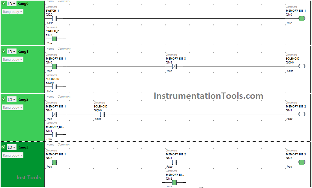
When Push Button 1 or Push Button 2 is PRESSED
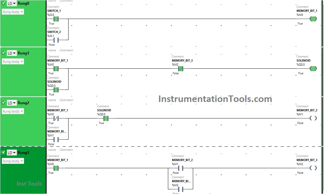
In Rung 0, Push Button 1 and Push Button 2 are connected in parallel implementing OR Logic Gate. So, when Push Button 1 or Push Button 2 is Pressed, Memory Bit 1 will turn ON in Rung 0.
In Rung 1, the Solenoid will turn ON as Normally Open Contact used for Memory Bit 1 in Rung 1 will be in a True State, and Normally Closed Contact used for Memory Bit 3 will be in a false State.
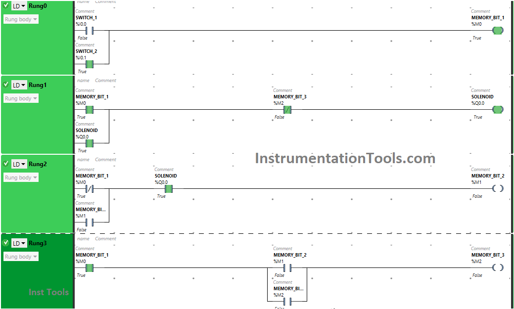
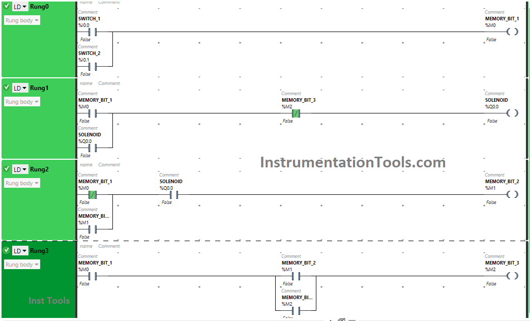
When Push Button 1 or Push Button 2 is RELEASED
When Push Button 1 or Push Button 2 is released, Memory Bit 1 will turn OFF in Rung 0 and Rung 1 but Solenoid will remain ON as Latching is used for Solenoid in Rung 1.
In Rung 2, signal will flow through Memory Bit 1 as Normally Closed Contact used for Memory Bit 1 will be in False State. Normally Open Contact used for Solenoid in Rung 2 will allow signal to pass through it as it is in True state and Memory Bit 2 will Turn ON.
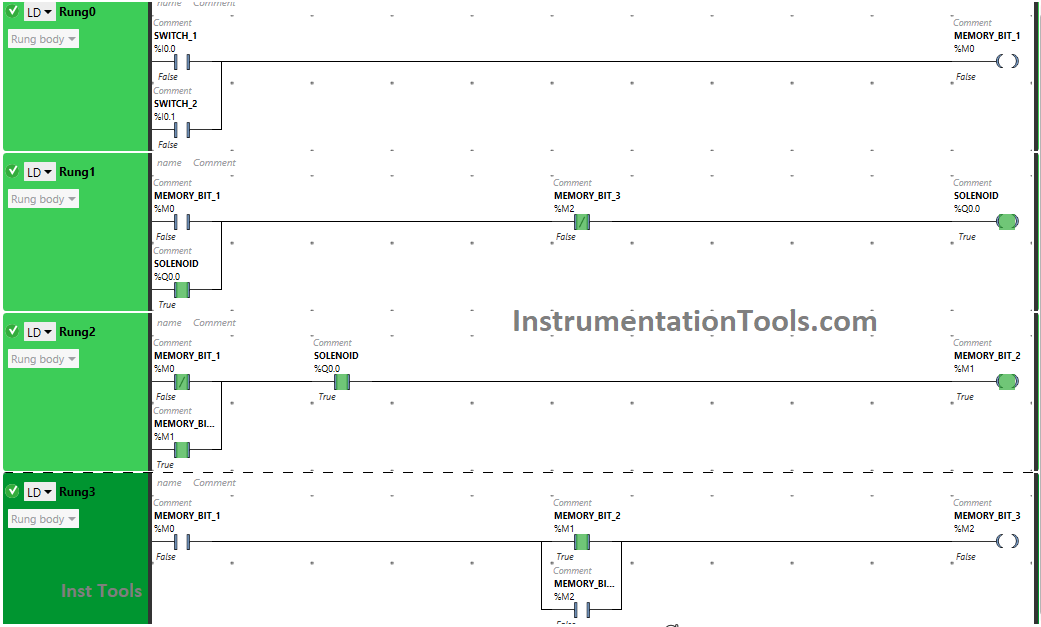
When Push Button 1 or Push Button 2 is PRESSED Again (Second Press)

Pressing Push Button 1 or Push Button 2 again will turn OFF the Solenoid because Memory Bit 1 in Rung 0, Rung 1, Rung 2 and Rung 3 will turn ON. Turning On Memory Bit 1 in Rung 3 will Turn ON Memory Bit 3 in Rung 3 and Rung 1.
So, Normally Closed Contact used for Memory Bit 3 in Rung 1 will be in true state and does not allow signal to pass to the Solenoid.
When Push Button 1 or Push Button 2 is RELEASED Again (Second Release)
When Push Button 1 or Push Button 2 is released again, Solenoid will remain OFF as Normally Open Contacts used for Push Button 1 and Push Button 2 in Rung 0 will be in false state and will not pass signal to the Solenoid.
If you liked this article, please subscribe to our YouTube Channel for PLC and SCADA video tutorials.
You can also follow us on Facebook and Twitter to receive daily updates.
Read Next:
- Basic PLC Alarm Programming Example
- Run 4 Motors Push button PLC Program
- Start Stop of one Motor PLC program
- PLC Automatic Control of Two Outputs
- PLC Motor Logic with TEST Pushbuttons