When you hear about PLC programming, the five used languages in it are – ladder logic, structured text, functional block diagram, sequential flow chart, and instruction list. Any language, once understood, can be used for writing an application code and running a machine properly.
Best PLC Programming Language
But often, new PLC programmers get confused as to what to use for writing a program. If he understands a language’s advantages and disadvantages, then he can easily determine what to use for writing a PLC program. So, it is necessary to understand the difference between them and define which language to use for coding. In this post, we will see which language is best for PLC programming.
Ladder Logic
Ladder Logic is the most basic type of PLC programming language. It can easily be correlated to an electrical wiring control diagram. Traditionally, electrical control wiring was used to operate outputs according to the inputs provided.
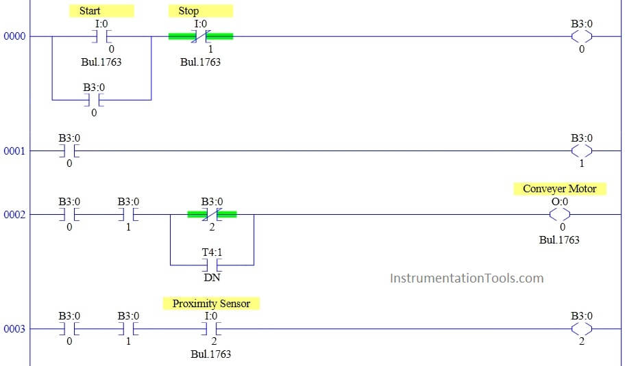
The ladder Logic drawing consisting of contacts and coils was implemented in the same way in the ladder logic programming. You have a series of rungs, each rung having contacts and coils. When the rung is powered up, the coil, depending upon its type, operates accordingly.
You can write as many rungs as required in a program and the code will execute accordingly. When you see it, the resemblance is similar to a ladder, and thus, the name is given ladder logic. Refer to the below diagram for understanding. You can see how simple it is to get through.
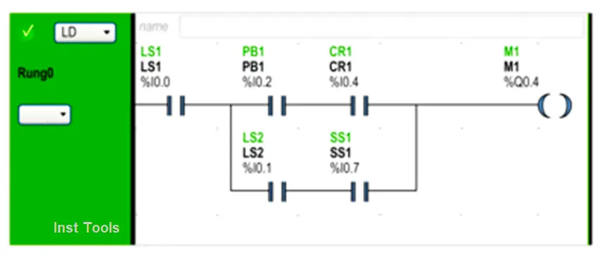
In the above illustration, inputs associated with a switching device in the relay logic diagram are shown as contacts in the Ladder Diagram. The M1 output coil in the relay logic diagram is represented with an output coil symbol in the Ladder Diagram.
The address numbers appearing above each contact/coil symbol in the Ladder Diagram are references to the locations of the external input/output connections to the logic controller. So, in between two end power rails, you can place the required elements and write the logic in them. The rungs execute in a cyclic manner from top to bottom.
Structured Text
Structured Text can be said as the local IT-level language. The resemblance of structured text language is very similar to codes that we write in a software language. As the name implies, Structured Text is a series of texts written in an assignment way.
Instructions must be terminated with semicolons. When an assignment is performed, the current value of a single or multi-element variable is replaced by the result of the evaluation of the expression.
An assignment consists of a variable specification on the left side, followed by the assignment operator: =, followed by the expression to be evaluated. Both variables (left and right sides of the assignment operator) must have the same data type. Refer to the below diagram for understanding.
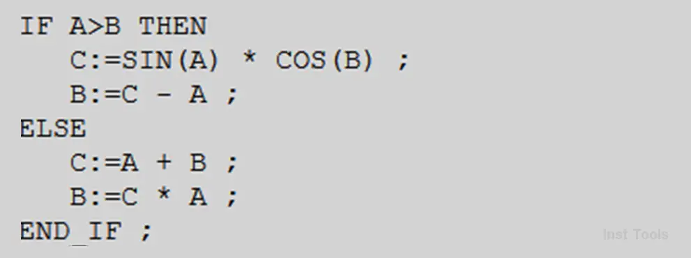
As you can see, it has different types of operations and conditions. In the above example, an if-else statement is used to evaluate an expression. If the condition is true, then the variable assigned on the output side turns on and when the condition goes false, then the variable will turn off. ST language is thus best for mathematical calculations, as it looks sober and easy to understand.
Sequential Flow Chart
A sequential Flow Chart is the most advanced tool when you want to write complex programs in a repetitive way or sequential way. As the name implies, SFC language allows you to write a program through a flow chart. It works in steps, branches, links, jumps, and transitions.
An SFC section is a “Status Machine”, i.e. the status is created by the active step and the transitions pass on the switch/change behavior. Steps and transitions are linked to one another through directional links.
Two steps can never be directly linked and must always be separated by a transition. The active signal status processes take place along the directional links and are triggered by switching a transition. Refer to the below image for understanding.
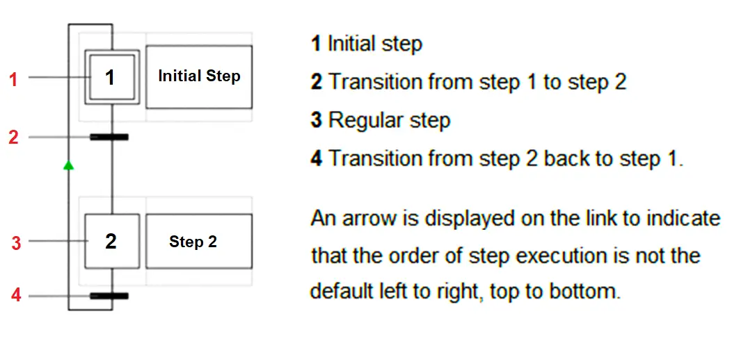
The direction of the chain process follows the directional links and runs from the end of the preceding step to the top of the next step. Branches are processed from left to right. Every step has zero or more actions.
A transition condition is necessary for every transition. The last transition in the chain is always connected to another step in the chain (via a graphic link or jump symbol) to create a closed loop. Step chains are therefore processed cyclically.
Functional Block Diagram
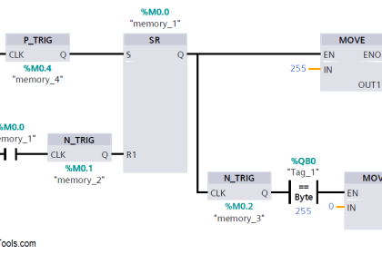
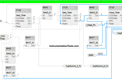
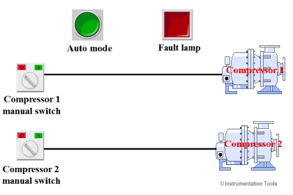
The Functional Block Diagram (FBD) language that is generally used in microprocessors, is available in a similar format in PLC programming too. It is a diagram of blocks connected with each other, with each block having its input and output.
FBD language is very easy to troubleshoot because you can literally view the whole code in a single view, rather than scrolling up and down. This helps in quick maintenance and also increases the efficiency of the programming. Refer to the below image for understanding.
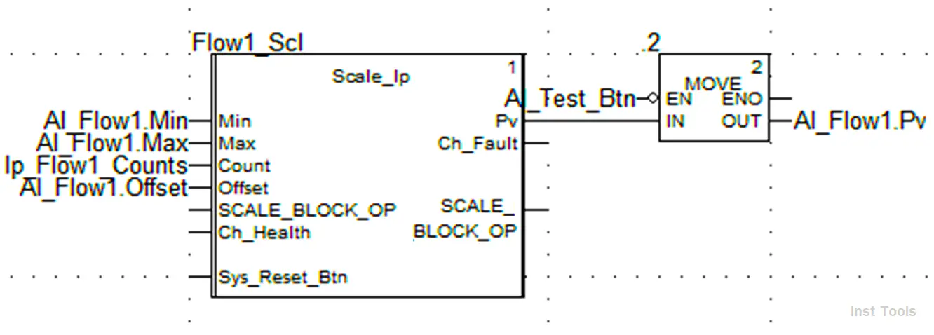
As you can see, you can connect various types of functions and blocks easily by lines, which shows how a flow is happening in the logic. You just have to assign input and output pins, connect the lines between these pins and your code works accordingly.
Instruction List
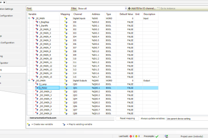
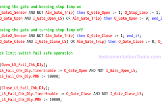
A program written in Instruction List language consists of a series of instructions that are executed sequentially by the logic controller.
Each instruction is represented by a single program line and consists of the following components – line number, current value which can be seen online only, instruction operator, and operand. Refer to the below image for understanding.
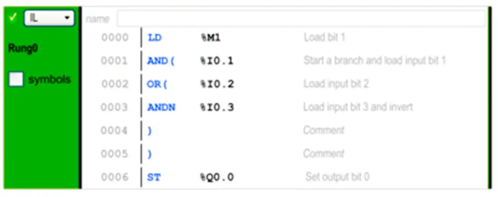
You can see that each line executes one single operation only. Instead of contacts and coils used in ladder logic, you have load instructions and set/reset instructions corresponding. It is a mixture of ladder logic and structured text. That is why, it is also called as similar to an assembly language. When you go online in the PLC, you can see animated values in this window.
When we see these five languages, we see that the most ones that are generally used by programmers are ladder logic, structured text, and functional block diagram. Every language has its merits and demerits. But, these three are simple to understand, interpret, and design. This helps the programmer in designing the logic properly.
That does not mean that the remaining two languages are not used. It depends on the skills of the programmer on what he has to use to implement the coding. So, it is difficult to comment on the best language; but yes, out of these three too, the most used is the ladder logic.
If you liked this article, then please subscribe to our YouTube Channel for Instrumentation, Electrical, PLC, and SCADA video tutorials.
You can also follow us on Facebook and Twitter to receive daily updates.
Read Next:
- Firmware Version of a PLC
- Sequential PLC Pneumatic Valves
- PLC Programmer Salary and Career
- How to Read the PLC Datasheet?
- Clock Memory Bits in Siemens PLC