Hello and welcome back with another STL lesson, if you are interested with SIEMENS PLCs and specially with the Statement List language.
Here is a series that discuss this language in detail and with practical examples.
So, if that is your first time on Instrumentation Tools, do not forget to check the previous lessons.
Timers in STL
Today we are going to explain two different types of timers using the STL language:
Also, we will give an example that discusses a common issue that happens in most plants.
Timer Properties with SIEMENS PLCs
Area in Memory
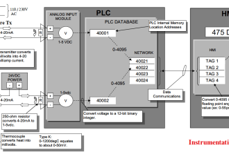
Timers have an area reserved for them in the memory of your CPU. This memory area reserves one 16-bit word for each timer address.
The number of timers depends on your PLC CPU version.
As we can see in the next figure the first 12 bits are reserved for the time value, and for (12 – 13) bits they are reserved for the Time Base.
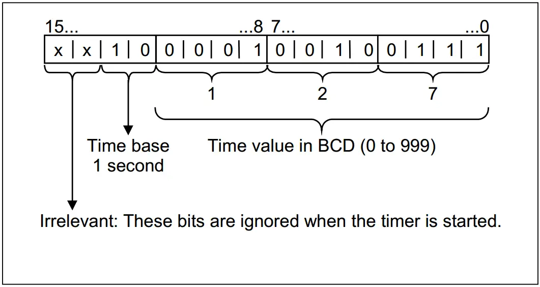
Time Value
You can pre-load a time value using either of the following formats:
Format 1:
W#16#txyz
Where t = the time base (that is, the time interval or resolution)
Where xyz = the time value in binary coded decimal format
Format 2:
S5T#aH_bM_cS_dMS
Where H = hours, M = minutes, S = seconds, and MS = milliseconds;
user variables are: a, b, c, d
The time base is selected automatically, and the value is rounded to the next lower number with that time base.
Time Base
Bits 12 and 13 of the timer words contain the time base in binary code.
The time base defines the interval at which the time value is decremented by one unit.
| Binary coded for the time base | Time Base | Range |
| 00 | 10 MS | 10MS to 9S_990MS |
| 01 | 100 MS | 100MS to 1M_39S_900MS |
| 10 | 1 S | 1S to 16M_39S |
| 11 | 10 S | 10S to 2H_46M_30S |
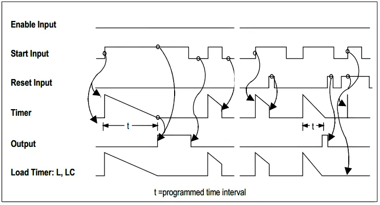
ON Delay Timer in STL
Format
SD < Timer > // data type for this instruction is a timer
Description
SD <timer> starts the addressed timer when the RLO transitions from “0” to “1”. The programmed time interval elapses as long as RLO = 1.
The time is stopped if RLO transitions to “0” before the programmed time interval has expired.
We can say that it delays the stating function, till the preset time finished.
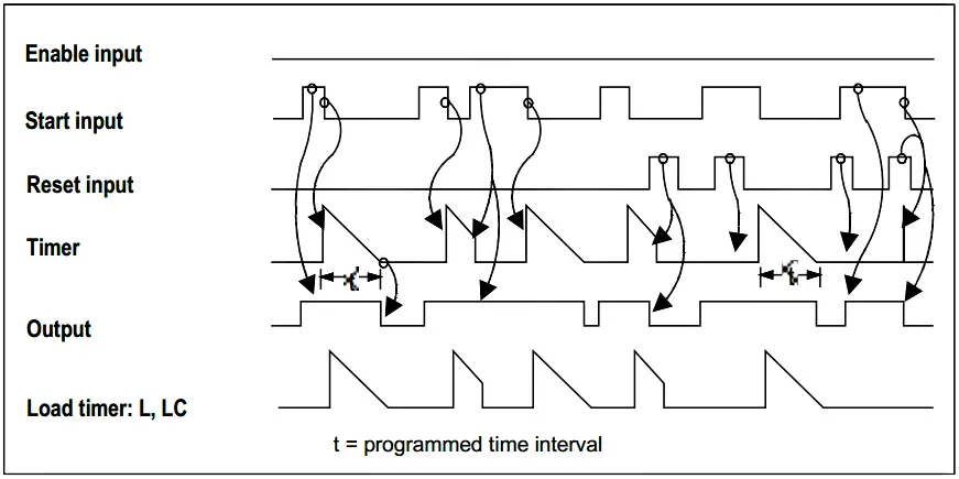
OFF Delay Timer in STL
Format
SF < Timer > // data type for this instruction is a timer
Description
SF <timer> starts the addressed timer when the RLO transitions from “1” to “0”. The programmed time elapses as long as RLO = 0.
The time is stopped if RLO transitions to “1” before the programmed time interval has expired.
We can say that it delays the stopping function, till the preset time finished.
Example Timer STL Program
A very common issue that occurs in several plants, is an instant high current consuming Spicks in your plant due to much of starting current taken by several motors that are turned ON at the same time.
The Electric Network of your plant will suffer from an Undervoltage due to these current spikes.
For equipment that it can not correctly operate at such low levels of incoming supply voltage, it may have serious damage to its components.
So, to avoid such a situation we need to start our plant motors in a sequence to eliminate the current consumption spicks.
By assuming that we have three motors that we need to operate them in order with a delay of 10 sec. we could program such a situation like that:
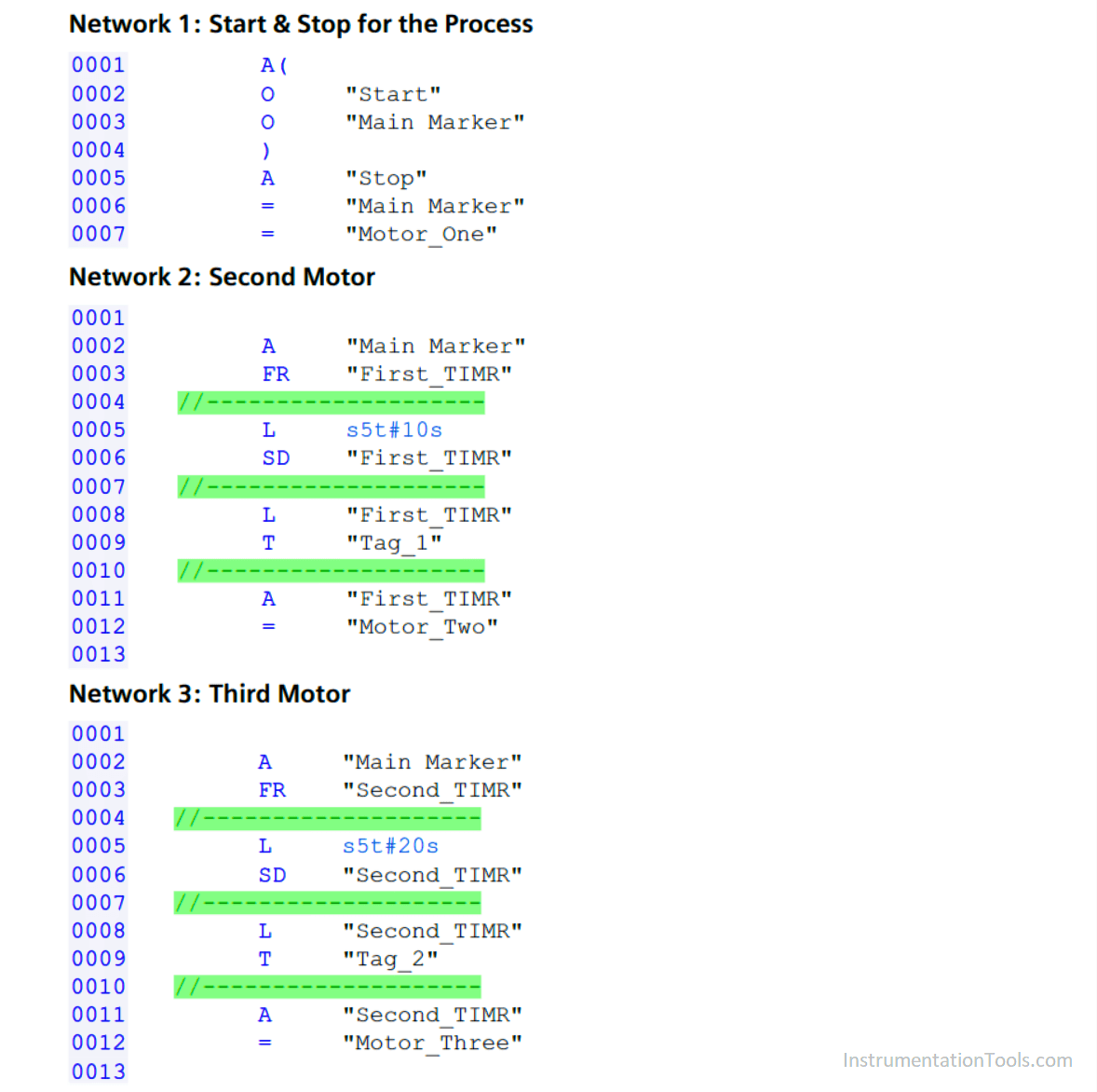
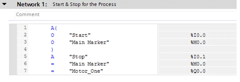
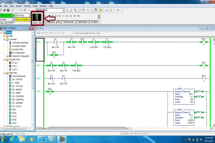
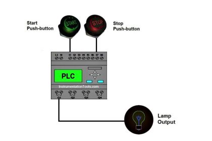
For the first network, we can see that the start and stop pushbuttons are attached to a marker, so when pressing start the Main Maker = True, and when pressing stop the Main Marker = False.
and also, as soon as we press start the first motor starts to run.
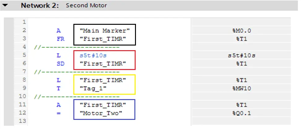
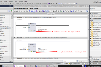
For the next figure that is an ON-Delay Timer that delays the starting of the second motor by 10 seconds, as we could see in the red box the timer is loaded with (10s).
For the black box, the input signal M0.0 enables the timer T1 by the FR instruction (free) this instruction is responsible for initializing the timer.
For the yellow box, we are just loading the timer counting value to another location of memory (MW10).
For the blue box, when the timer reaches the preset time value it will launch the output bit Q0.1 that is responsible for starting the second motor.
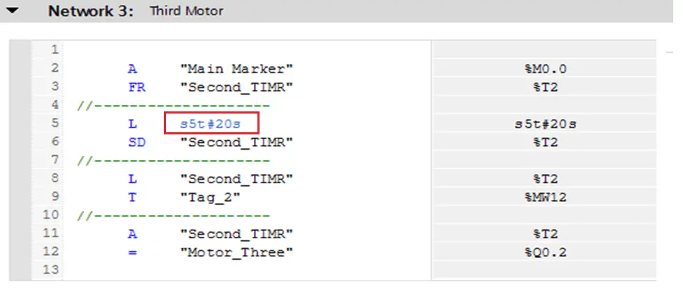
Here is another timer for the third motor but you can notice that the preset time is 20 sec to maintain the delay time between the three motors to be 10 sec.
That is all for now, and if you want to get a try you can make the same logic but instead of the motors are starting in sequence what about if we want to stop them in sequence also.
Give it a try using the STL language and if you are facing some issues you can post your questions using the below comments form.
Reference: Statement List for S7-300 and S7-400 Function Manual
If you liked this article, then please subscribe to our YouTube Channel for PLC and SCADA video tutorials.
You can also follow us on Facebook and Twitter to receive daily updates.
Read Next:


Could you provide explanation for math functions using STL programing for seimens s7- 400
Hi, thanks for the info. Just a quick question, how do I know which “T#” to use? Do i just pick a random number or ?
Many thanks
Tsepo.