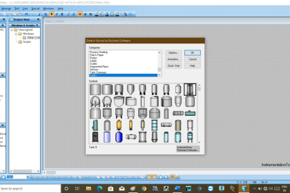
Welcome back with our Basic “PLC Programming Training” in the previous post we learned how to download and install LogixPro software and how to deal with the software platform.
Today we are going to proceed with the first PLC example in our training by programming the Batch Simulator.
The main advantage of this series is that we will not learn the programming of just the Batch process or the programming of traffic simulation, today and for the next posts, we will put together a few Basic Rules that would boost your programming skills in general.
What is meant by the Batching Process?
The operation of a batch-size production mill is simple and effective. The raw material that would be cooked has to be placed with grinding media in a stationary, jacketed tank.
After carrying out some industrial processes such as (heating, mixing, …) the whole mixture is ejected from the tank by a discharging pump.
This kind of process is commonly used in many factories with the difference in the type of material being mixed.
Basic steps for PLC programming
As we said before PLC programming does not need a talented engineer as much as it needs an organized person, here we have basic steps that we need to follow for coding any PLC application:
- Clarifying the operation sequence and interlocks in the form of short and concise sentences “AFD”.
- Identifying the application Input/output signals “making an I/O list”.
- Start by converting the AFD to the Ladder Logic Instructions.
Step by step and always remember, “start simple… and finish simple”.
- Commissioning the PLC program by downloading your code to the PLC and troubleshooting the bugs and errors, then with swift editions now your code is ready.
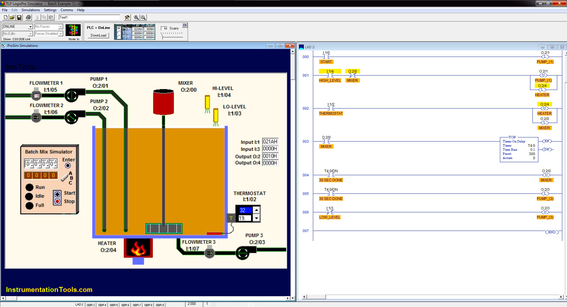
Batch Simulator using LogixPro PLC Simulator
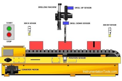
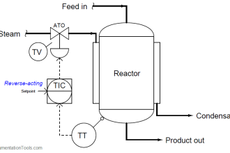
As we discussed earlier in the operation of the batching process, now we are going to start with the first step by summarizing the whole application shown in Fig. (2) in the form of short sentences:
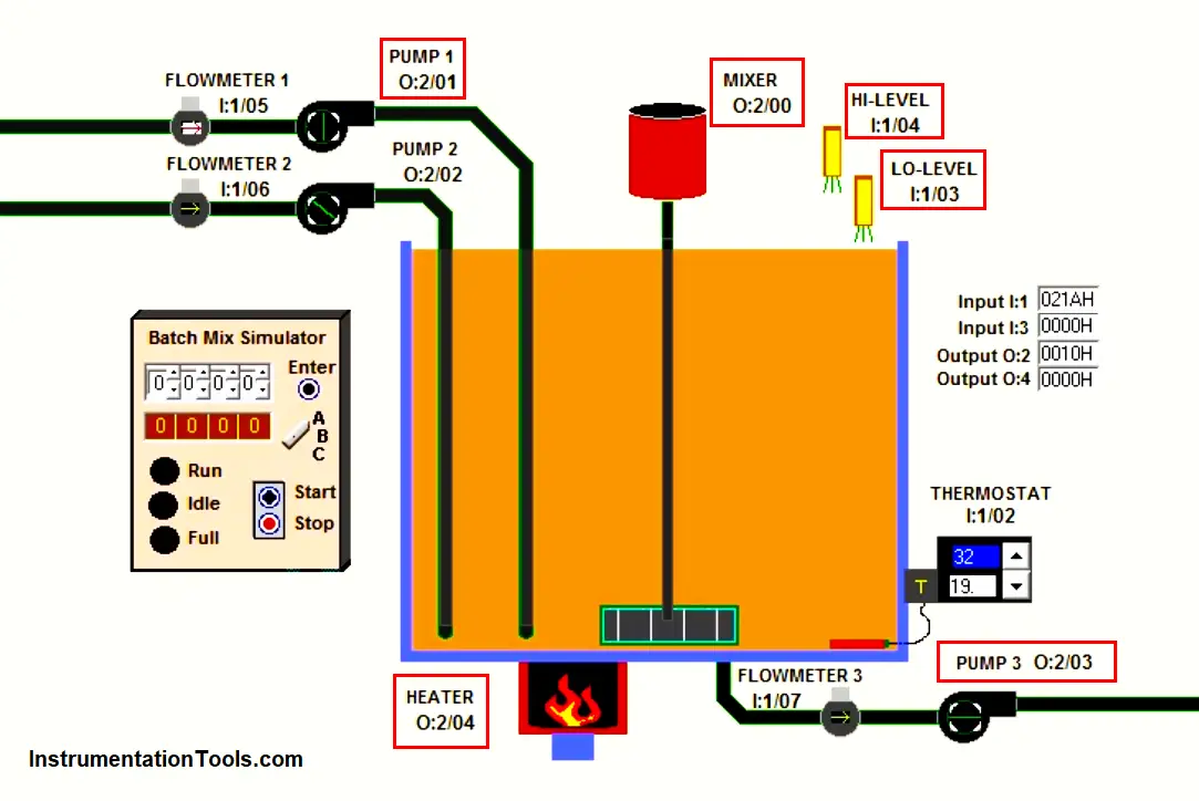
- By pressing the start push button, “PUMP_ (1)” which is responsible for filling the tank, should turn on to start the filling operation.
- Once the level of the fluid reaches to the HIGH_LEVEL_SWITCH, “PUMP_ (1)” should turn off. Fig. (1)
- Then the HEATER should operate till the thermostat reaches the set point.
- Then using the MIXER for mixing the fluid for 30 Sec.
- Finally, the whole fluid should be discharged using “PUMP_ (3)”
The Application I/O Signal List
Now and after we have discussed and summarized the batching process operation the next step is to clarify the Input and Output signal list as followed:
| Function | Address |
| START | I:1/0 |
| STOP | I:1/1 |
| HIGH-LEVEL | I:1/4 |
| LOW-LEVEL | I:1/3 |
| PUMP (1) | Q:2/1 |
| PUMP (2) | Q:2/3 |
| HEATER | Q:2/4 |
| MIXER | Q:2/0 |
| THERMOSTAT | I:1/2 |
Translating the batching process conditions into Ladder instructions
Always remember that programming is not as hard as you imagine all you need is to start step by step and whenever you feel that your PLC code becomes to be complicated and not organized, be sure that you are on the wrong path.
NOTE
“Before we start to discuss our solution, it is very important to give it a try by yourself for just 15 min.”
- Now by starting with the first condition which is by pressing START, PUMP-(1) should turn on.
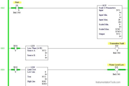
As we can see in Fig. (3) for the first rung “000” whenever we press the START button it will energize the Latching coil for the output that is responsible to operate PUMP-(1).
- Regarding the application AFD, PUMP-(1) should be turned ON till it fills the tank (HIGH_LEVEL energized).
So, for the second rung (001) as you can see when the HIGH_LEVEL switch will indicate the level it will de-energize the filling pump “PUMP-(1)” and also it will latch the HEATER to increase the fluid temperature.
- And now is the role of the THERMOSTAT when the temperature of the fluid reaches the setpoint temperature that is represented in Fig. (1), the THERMOSTAT NO contact will be closed and it will de-energize the heater operation and it will energize the MIXER to start mixing the fluid as shown in rung No. (002)
- Notice that there is an interlock between the heater and the mixer represented in Fig. (2) rung No. (001), as you can see there is an NC contact for the mixer on the HEATER coil so the heater can not be turned on when the mixer is ON.
- Now as shown in rung No. (003) the mixer will initialize a timer (T4:0) to calculate 30 Sec. of working for the mixer then the timer will de-energize the mixer as shown in rung No. (004)
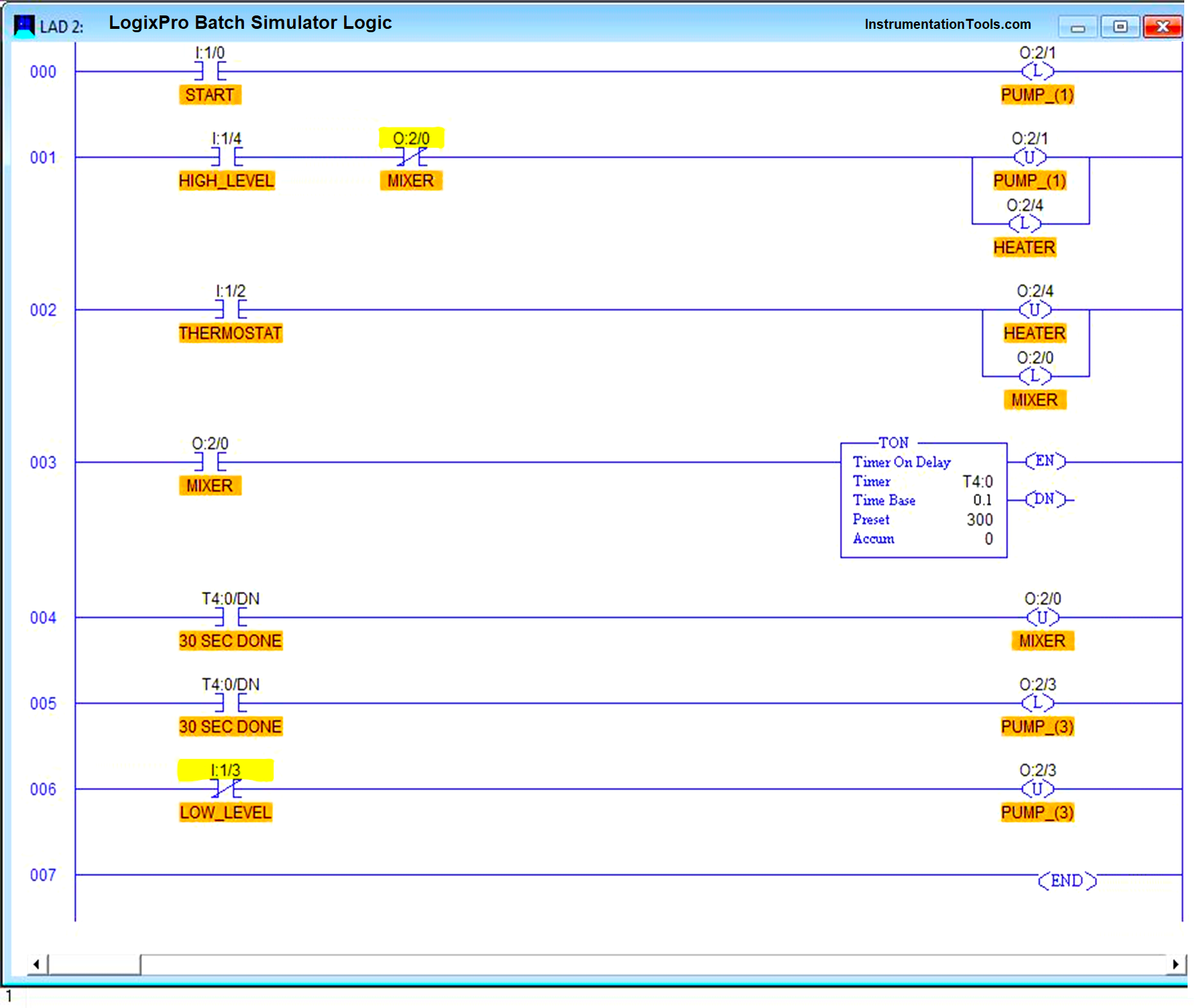
- At the same time and after the timer stopped the mixer, it will energize the discharging pump “PUMP-(3)” as shown in rung (005) till the tank get empty and the low-level switch will de-energize the discharging pump as shown in rung No. (006)
- The whole process will be repeated if we press start again.
Watch the PLC Simulation
In the below video, the ladder logic of the batch simulator is simulated in the Logixpro PLC software.
Commissioning the PLC Program at the Site
Now we have the last step, to download our PLC code and to try it on the real site.
You may have some problems at the beginning but if your code is organized and simple this step will not cost you a big deal of time.
PLC Exercise for Yourself
You will never learn to program if you are just satisfied with watching, you have to try by yourself.
So, we did not mention how to stop this operation?
If we need to stop this operation at any stage (Filling, Heating, Mixing, Discharging) by pressing the stop push button and by pressing start again the operation should proceed where it stopped, what we need to edit in our code to make that possible??
Write your solution in the comments below and let us see if can you do it or Not…